
SpeedFit™ Design Simulator
Simulate and evaluate the performance of SiC-based power circuits and determine the right SiC device in seconds.
Start a SimulationCRD250DA12E-XM3 Consequence of frequent switch tripping

Hi,
I am currently using the CRD250DA12E-XM3 inverter to supply a test-rig used to examine short circuit faults.
I have a downstream MCB that is intended to provide protection during abnormal short-circuit current conditions. During one of these abnormal events, the 3A-rated MCB trips as expected. However, the inverter switches also trip and enter a latched-off state; although the short-circuit current shouldn't exceed the inverter’s rated current.
What could be causing the inverter to trip in this situation? And if this occurs relatively frequently, could it result in any permanent damage to the inverter?
Many thanks.
Kind regards,
Comments
-
Thank you for your post, it has been approved and we will respond as soon as possible.
0 -
Hello ZAO,
Can you explain the sequence of events during the abnormal short-circuit conditions that you are describing? Are one or more of the power modules being subjected to a short-circuit event?
Silicon carbide (SiC) MOSFETs such as the XM3 power modules used in the CRD250DA12E-XM3 reference design switch extremely fast. Since they switch so fast, they can conduct very high currents and must dissipate extremely high energies over short durations (<2 us). All this high current/energy occurs before legacy protection devices such as MCBs ever recognize the fault. If you have a fault condition that is shorting one or more of the XM3 power modules, the onboard protection included in the XM3 gate drivers will fault before the MCB in order to protect the device.
The devices can sustain short circuit events, assuming suitable protections are in place to avoid extended short circuit events (the CRD250DA12E-XM3 includes those protections by default). However, these events place significant stress on the MOSFETs and should be avoided since multiple short circuit events can degrade the lifetime of the power module(s). The onboard short-circuit protection should only be used as a final fail-safe and should not be used in normal operation. More information about short circuit events can be found in the Wolfspeed application note titled "SiC MOSFET Short Circuit Application Note" (PRD-08296).
Thanks,
Chris N.
0 -
Hi Chris,
Thank you for your response.
I expect the sequence of events to be as follows:
- I have two conductors separated by a layer of insulation, connected to the line-to-line output from the CRD250DA12E-XM3 inverter
- After a period of time of stressing the layer of insulation, it breaks down and leads to a short circuit path between the two line outputs, resulting in a high current flow, causing the switches to trip, along with my MCB and power supply
- I have limited the current on my DC power supply to 30 A, but I am unsure how this would interact with the inverter and whether this limitation would work
Another interesting observation is that sometimes the switches do not trip during this short circuit event; instead, my MCB and the power supply trips and the CRD250DA12E-XM3 capacitor discharges to 0 rapidly while the switches remain on.
To further protect the CRD250DA12E-XM3, would it be sufficient to add a series resistor and inductor to limit the current during a short circuit event?
Many thanks.
0 -
Hello ZAO,
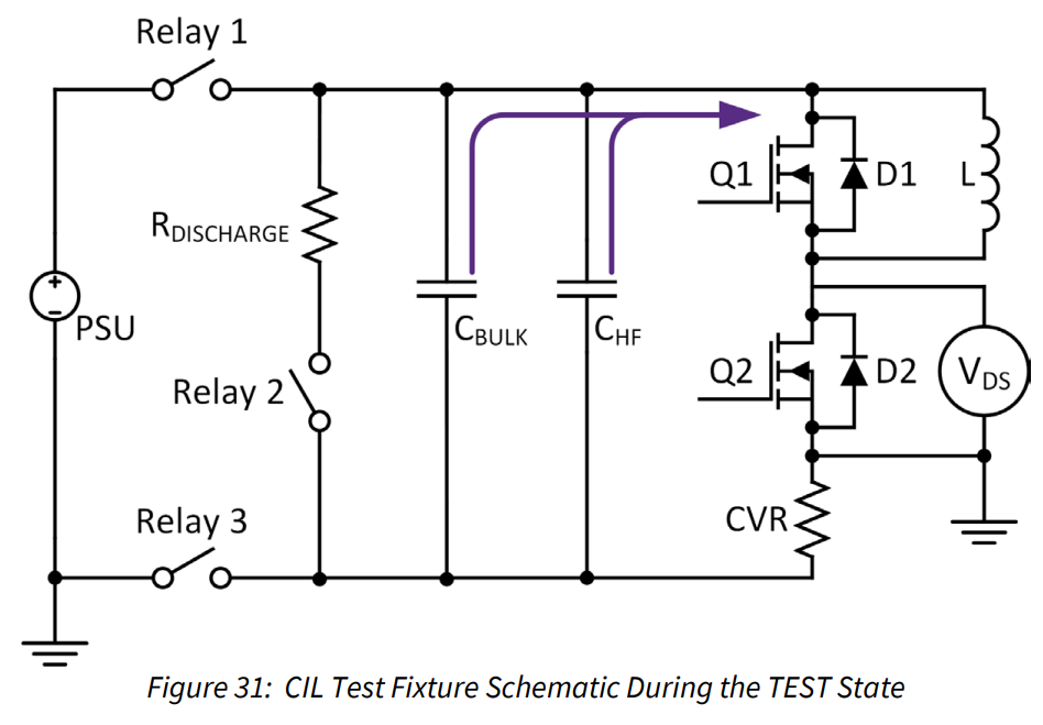
Based on your described test conditions, it seems that the overcurrent protection circuits on the XM3 modules are operating as expected to save the devices. When you have a normal short-circuit event, there is plenty of energy in the capacitor bank to provide several kA of current to the load through the modules, independent of the power supply limits. In internal short-circuit testing, we run the short-circuit test strictly off a capacitor bank energy using the same techniques as our CIL testing described in PRD-08333 (picture below). Since the short circuit event is such a short duration, the capacitor bank can provide all the necessary energy. As mentioned before, the overcurrent protection circuit on the XM3 gate drivers reacts extremely quickly (<2us) to limit current/energy in the module during a short-circuit event. It is not a surprise that is reacts to the short circuit event faster than MCB.
In the cases where the overcurrent circuits do not trip (as you described), I predict that in those cases, the insulation layer is not fully breaking down. Thus, in those cases, the overcurrent protection circuit on the modules is not tripped. You still may have high currents (hundreds of amps), which can be handled by the power modules (assuming you have the cooling configured correctly). However, in these cases, the capacitors do not have enough stored energy to sustained this current, which is why you hit the current limit on the power supply as the capacitors deplete.
In your current configuration, this is not a recommended use of these modules. You are causing repeated short-circuit events on the modules, which might be subjected the modules to several kA each time. At a minimum, I would add series impedance to the circuit to limit the inrush current, as you suggested. I believe an inductor would be better, assuming it has a high enough inductance to suitably limit the current and that it will not saturate. I recommend simulating this setup using the Wolfspeed LTspice model of the XM3 power module to understand the fault and to determine the required load to perform this test repeatedly and safely.
Thanks,
Chris N.
0 -
Hi Chris,
Thanks for the comprehensive explanation; it was very insightful.
As recommended, I ran a quick simulation. It confirms that a series impedance consisting of both inductance and resistance is sufficient to limit the fault current to approximately 20 A peak. This should allow the MCB enough time to trip safely without relying solely on the XM3 modules' inherent protection.
However, sourcing an inductor that matches the XM3 module’s specific requirements (rated inductance, voltage, current, resonant frequency, fundamental frequency, and switching frequency) is more difficult than anticipated.
I have found a line reactor in stock that relatively matches the criteria: RS Group - Sine Wave Filter/Line Reactor. It is rated for a 50 Hz fundamental, 8 kHz switching frequency, and a 690 V maximum.
While these specs are below the XM3’s full ratings, given that the inductor will only be active for a very short duration during a short-circuit event, do you believe this lower-rated component would be sufficient? Alternatively, if you could recommend any specific inductors suitable for use with the XM3 module, I would greatly appreciate it.
I look forward to your insights.
Many thanks,
0 -
Hi ZAO,
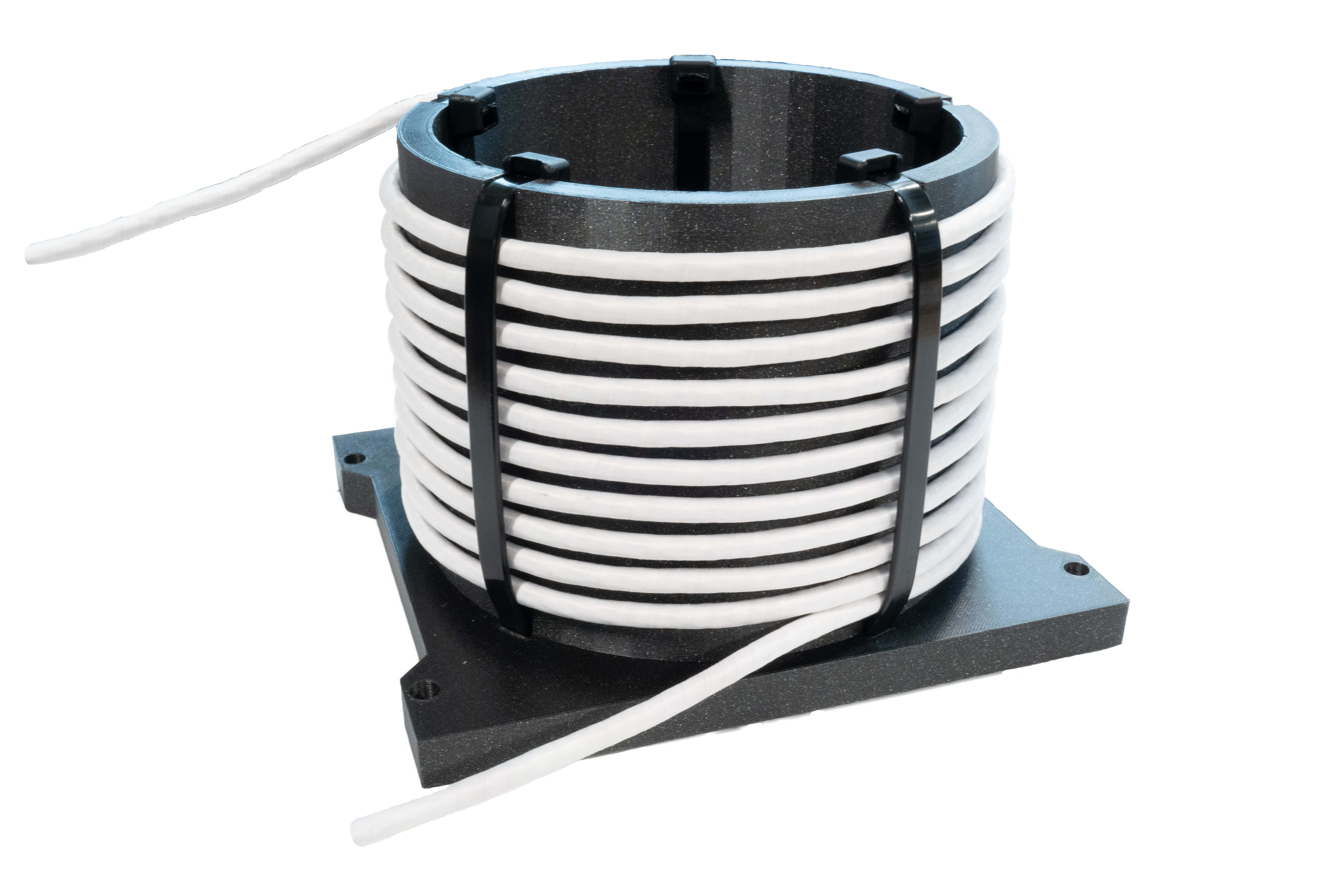
If you are not spaced constrained (it doesn't seem like you are since this sounds like a laboratory test setup), we recommend using Litz wire wrapped around an air core such as a PVC pipe. Using an air core prevents saturation, and the Litz wire should enable high switching frequencies. You can add turns until you reach the desired inductance. Below is an example custom inductor wrapped around a 3D printed air core. There are also some additional details about the inductor that we recommend for clamped inductive load (CIL) testing in Section 3.1 of PRD-08333.
Thanks,
Chris N.
0 -
Hi Chris,
Thank you for the clarification.
One last question: for the XM3 module, is there a risk of damage when operating at a low current magnitude such as 20 A, but with a high di/dt?
Many thanks.
Kind regards,
0 -
Hi ZAO,
It is fine to operate the modules in that configuration.
Thanks,
Chris N.
0 -
Hello ZAO,
I hope that this answered your question. I will close this discussion for now but if you have a follow up question, please "Start a New Discussion" and we would be glad to support you further.
Thanks,
Chris N.
0