
SpeedFit™ Design Simulator
Simulate and evaluate the performance of SiC-based power circuits and determine the right SiC device in seconds.
Start a SimulationAdditional Analog Input for Grid-Side Measurement on CRD25DA12N-FMC

Hello,
I am working on a grid-tied application, and planning to buy the Wolfspeed 25 kW FM3 Three-Phase Inverter (CRD25DA12N-FMC) with the TI control card.
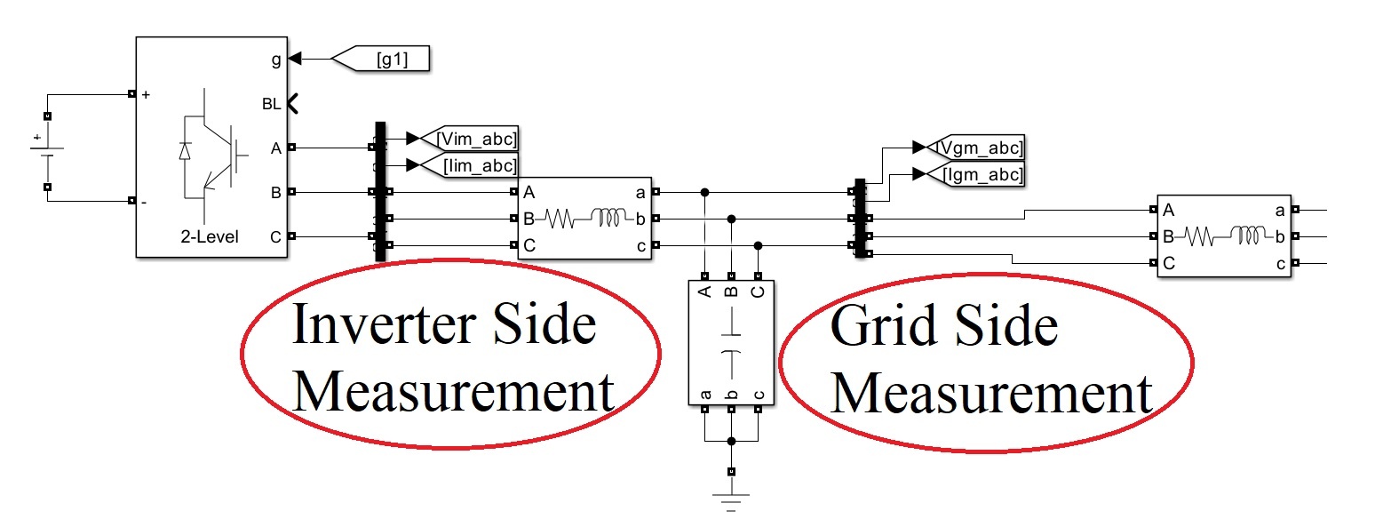
For control purposes, I need to measure both:
- Inverter-side voltage and current (already available)
- Grid-side voltage and current (additional 6 measurements)
From the datasheet, I see that:
- Hall-effect sensors provide inverter-side current measurement.
- Phase measurement pins can be used for inverter or grid-side voltage.
- The board has a Spare Connector Pinout (J8) with some extra ADC and GPIOs.
However, I need 6 more analog measurements, but I am unsure whether the Spare Connector Pinout (J8) can be used to feed these measurements directly to the TI control card.
Could you please confirm if these spare pins are suitable for additional ADC inputs? If not, do you recommend adding an external ADC module or using a multiplexer?
Thanks for your support!
Comments
-
Thank you for your post, it has been approved and we will respond as soon as possible.
0 -
Hello SMSHR,
Thank you for your interest in this product. On the "Spare Connector", two of the pins can be used for ADC measurements. Those pins are connected directly to the TI controlCard. The other pins can be used for spare GPIOs. We have not needed additional ADCs in our testing, so we do not have a recommended approach for adding more ADCs. We will consider this in future revisions.
Thanks,
Chris N.
0 -
Hello Chris,
Thank you for your response.
I have another question. Can I use an external microcontroller for the setup instead of using the TI control card that comes with the setup?Thanks,
Rafin
0 -
Hello Rafin,
We have not tested the system with an external microcontroller. I anticipate several challenges with using an external microcontroller since the circuit board routing and filtering is optimized for the current microcontroller in its current location. You would likely need to "hack" several parts of the board to try to add an external microcontroller and even then you may face signal integrity issues due to the hack. We do not support any external microcontrollers, so you would have to troubleshoot any challenges yourself.
Thanks,
Chris N.
0 -
Hello Chris,
Thank you for your reply.
Could you please recommend a setup with only the combined SiC inverter and gate driver circuit? I can build separate sensor boards and microcontroller boards.
I have a few more questions: Can I use the spare GPIOs as ADCs? Can we order a modified setup having additional ADCs and GPIOs? Do the SiC MOSFETs require snubber circuits?Thanks,
Rafin
0 -
Hello Rafin,
You could consider using our dynamic characterization evaluation board (KIT-CRD-CIL12N-FMC) but you will have to evaluate whether it meets your needs. This board is normally only used for dynamic characterization such as clamped inductive load (CIL) tests. Modifying it for continuous operation would at a minimum require looking at whether the onboard current shunt can operate at your intended continuous loads.The spare GPIOs cannot be used for ADCs on the onboard controller since not all the pins have ADC functionality.
With a low inductance design, these modules do not need a snubber. If you use either the KIT-CRD-CIL12N-FMC evaluation board or the CRD25DA12N-FMC three-phase inverter, you will not need to add a snubber since both these boards have low-inductance designs.
Thanks,
Chris N.0 -
Hello Chris,
Thank you for your prompt response.
I have a couple of quick questions:
- What is the rated current of the KIT-CRD-CIL12N-FMC? Our setup uses 400 V DC input and 10 A, with 220 V AC output at 10 A.
- Does the kit include SiC switches (Six-Pack module), or is it only for use with an external module? I also didn’t see any heatsinks—are they included or recommended separately?
Thanks again for your help.
Best regards,
Rafin
0 -
Hello Rafin,
Again, we do not have a design that is an exact match for your needs. The evaluation kit I mentioned would likely need modifications to fit your application needs since this design is intended for dynamic characterization (clamped inductive load tests and double pulse tests) which only take ~100 us. See PRD-08333 for more information about how our evaluation boards are normally used. You will need to carefully review the design files to see if it fits your application since we do not have testing data to indicate whether the board will work in continuous operation. My recommendation would be to use the CRD25DA12N-FMC design with less analog inputs since this will be a quicker path to getting your system operational. Furthermore, that board has test data for operating in a continuous configuration. I addressed your questions about the evaluation board below:
- The setup has been used to do short pulse characterization to >100 A. However, we have not used it for any continuous applications, since that is not its intended use. With a proper heat sink, it should work at the low currents you indicated. Again, you will need to review the files yourself to make the decision of whether you want to try it.
- The kit does not include the module or gate drivers. These must be purchased separately. The kit also does not include a heat sink since the module is generally mounted to a hot plate for externally heating the module during characterization.
Thanks,
Chris N.
0 -
Hi, I hope that this answered your question. I will close this discussion for now but if you have a follow up question, please "Start a New Discussion" and we would be glad to support you further.
0