A question about the SpeedFit simulation tool
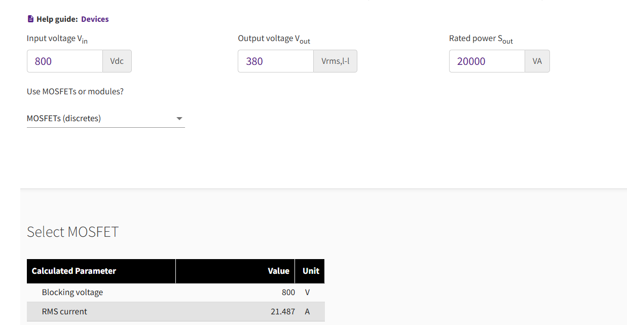
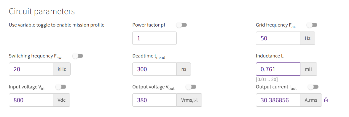
When I use the simulation tool with the application of 'Three Phase 2-Level Inverter', and set the detailed parameters as the Fig.1 showing below, it can be seen that the RMS current is calculated to 21.487A. But actually, the phase current(RMS) of 3P2L inverter under the provided parameters should be 30.387A, which is consistent with the result in the Fig.2. So could you please tell me what is the RMS current 21.487A referred to, and how to get this calculation result? I will be pretty grateful if the technical expert can give me a reply. Thank you.
Fig.1
Fig.2
Comments
-
Thank you for your post, it has been approved and we will respond as soon as possible.
0 -
Hello,
You are correct that with your settings, the RMS phase current will be 30.387 A. However, it's important to note that the device conducts only for half of the time. Therefore, we can approximate that the current flowing through one device in a leg resembles a half sine wave.
For a half sine wave, the RMS value is given by Ipeak/2. In this scenario, the RMS current through the device can be calculated as:
RMS Device Current = (RMS Phase Current) / sqrt (2)
This results in:
30.387 A / sqrt (2) ~ 21.49A
Thus, the quantity mentioned in the SpeedFit's Devices section refers to the RMS device current. You can also see this reflected in the simulation section, where the MOSFET RMS current is recorded as 21.477 A.
If you have any further questions, please feel free to ask.
Best regards
0 -
Hello,
Thanks for your detailed reply, I've understood that the quantity in Devices section refers to the RMS device current, and 30.387A refers to the RMS phase current. However, the aforementioned conclusion seems not synergy with that in T-NPC simulation, so please allow me to ask one more question.
In the Device setting section of T-NPC simulation (Fig.1) , the value of RMS current is 30.387A, which is consistent with the result in circuit section (Fig.2). Could you please tell me why the results are same in 3L inverter. I want to know the difference of RMS device current calculation between 2L inverter and T-NPC 3L inverter, and which parameter, peak current or RMS current is the main criteria to choose the power device in engineering practice.
Fig.1
Fig.2
0 -
Hello,
Thank you for bringing this to our attention. You are correct that the calculation of RMS device currents in the Device section of T-NPC simulation appears to be showing incorrect values. We are currently investigating this issue and working on rectifying it.
We appreciate your patience as we work to resolve this matter, and we will provide an update as soon as we have answers. Thank you again for your insightful observations!
Regards
0 -
Thanks for your prompt reply. I'm looking forward to the update.
Best regards
0


