
SpeedFit™ Design Simulator
Simulate and evaluate the performance of SiC-based power circuits and determine the right SiC device in seconds.
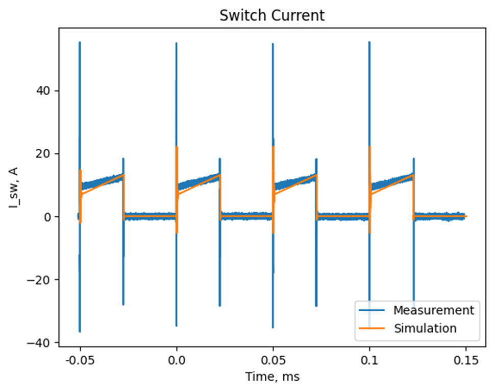
Start a SimulationCurrent peaks during the operation of the asynchronous boost converter

Hello,
I have been doing measurements with the MODMBHB0900V40A motherboard together with the MODACCBUCKBOOST190uH filter board in the asynchronous boost converter configuration. MODPWRMMC3M0045065K daughter card is being tested. I am using a power resistor of 17 Ohms with a 100 V output voltage operating at 20 kHz. The waveforms follow the expected shapes, however, the current peaks for the bottom switch during the turn-on exceed 40A, as can be seen in the picture below. The documentation says that the maximum continuous current for both boards is 40A, however, I could not find what is the maximum peak current.
Could you provide advice on what current peaks are safe to operate within?
Nils
Comments
-
Thank you for your post, it has been approved and we will respond as soon as possible.
0 -
Hello,
I was wondering whether there have been any updates regarding this question?0 -
Hello NiLs,
The current peaks you're observing during power testing are probably exaggerated. The current shunt for the system testing is designed for estimating the RMS current through the switch. Please stay below 40A rms current and the maximum junction temperature (Consider 120 C measured case temperature derating) of the device and you should be good. If you want to measure accurate peak currents, you can set the daughter card up for Dynamic measurements as detailed in section 5 of the User-guide. Let me know if you have any other questions. Thanks!
0 -
Thank you for the response! It is clear.
Kind regards,Nils
0