
SpeedFit™ Design Simulator
Simulate and evaluate the performance of SiC-based power circuits and determine the right SiC device in seconds.
Start a SimulationReverse recovery losses not calculated in PLECS using Wolfspeed's XML

Hello,
A couple of weeks back, I received an under-development XML file for the Wolfspeed CAB5R0A23GM4 from Blake. I created 1500V a boost converter model using the Wolfspeed custom MOSFET component and the XML file to get the junction temperature and losses.
I noticed that the model doesn't seem to calculate the diode reverse recovery losses, even though it is modelled in the XML.
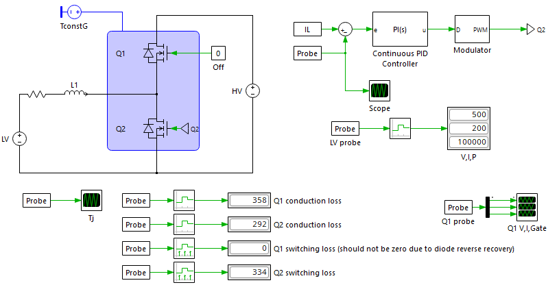
Am I using the model incorrectly in any way? I have attached the model and XML to this post. It would be good it somebody could take a look at it.
Comments
-
Thank you for your post, it has been approved and we will respond as soon as possible.
0 -
Hi Prathik,
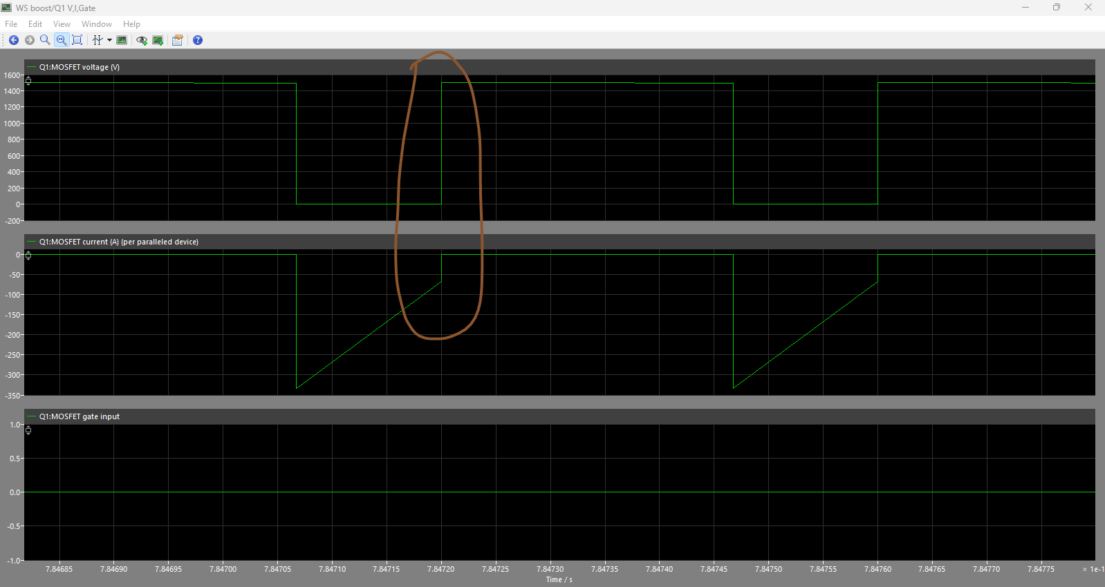
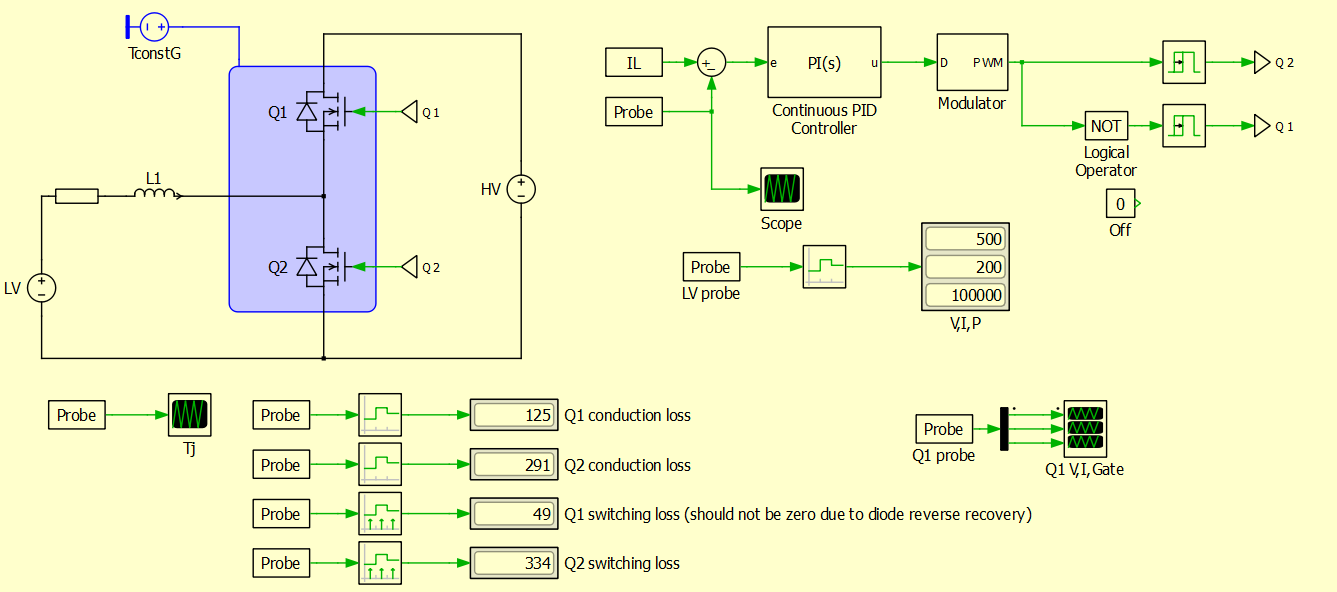
That's an extremely reasonable concern: it simply comes down to how the losses are calculated in PLECS. As you are likely aware, PLECS completely disconnects the thermal domain from the electrical domain for simulation speed. For turn-off switching losses specifically, it looks at the values of your input state variables (e.g. current, voltage, temperature) at the time step where switching occurs (i.e. your gate goes from logical 1 to zero), and finds the energy in the lookup table for those conditions. It then injects the correct losses into your thermal system. Since Q1 does not have a gate transition, the model does not consider there to be any switching event to pull a loss value from the lookup table. If I instead switch Q1 on when Q2 is off, you can see we now get switching losses in Q1:
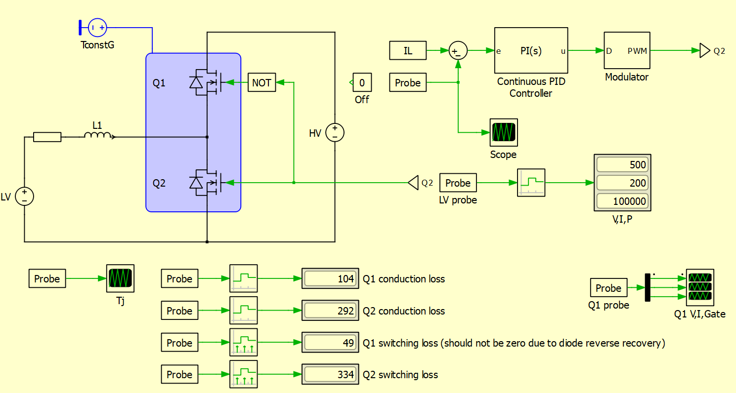
As you have realized, this behavior means that switching losses are normally uncounted in asynchronous converters. In the example, conduction losses have dropped by 70% in Q1 since the device is gated on when conducting (which is far higher performance than using the body diode). While I would not recommend asynchronous switching due to the high losses of the body diode, if you do need to investigate asynchronous losses, you can do so by making this modification to the simulation:
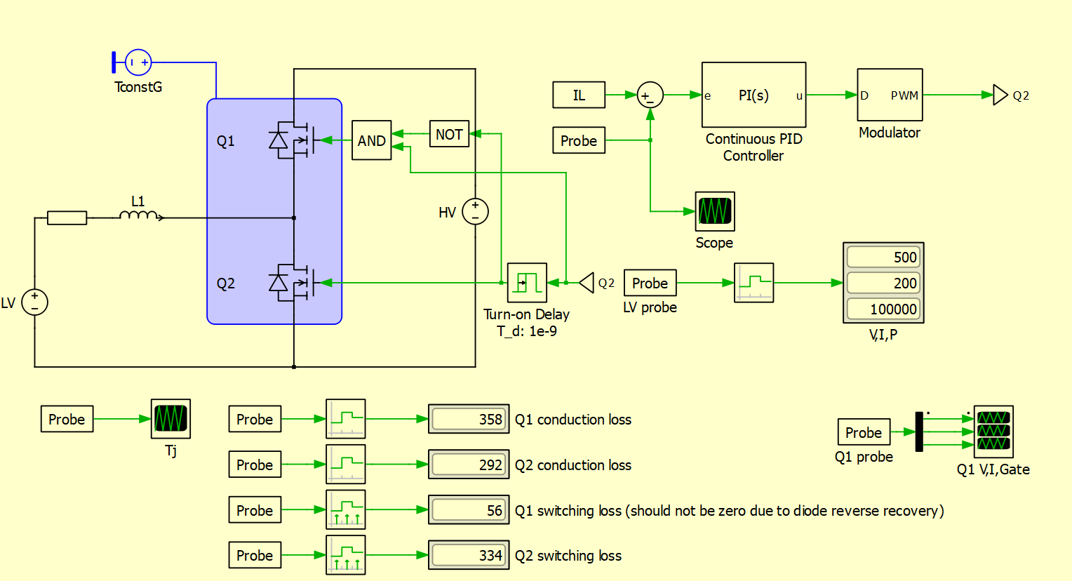
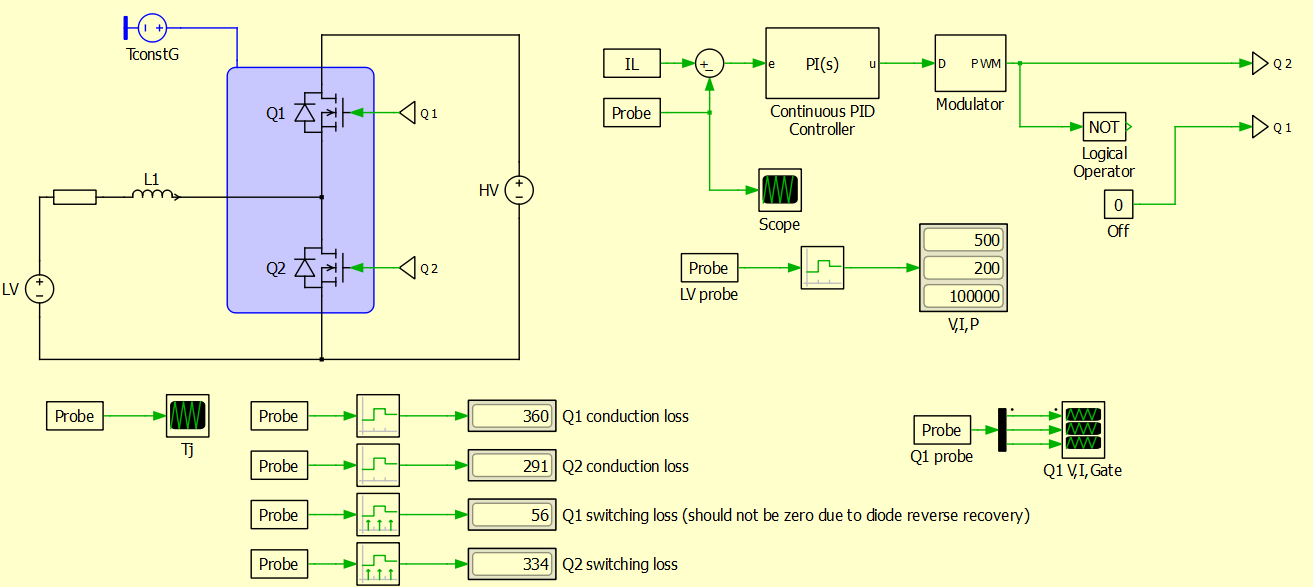
In this case, Q1's gate turns on briefly (for the length of T_d) right before Q2 turns on. You can see the conduction losses have returned to their previous level while we still have switching losses. In some sense we are tricking Plecs into counting the switching losses here, but it should be fairly accurate.
One note, while testing your simulation, I realized I had made a mistake in our "Eoss" table which is tucked into the model. I've made a new version that fixes this issue by clamping the Eoss losses to zero for negative current.
Let me know if you have any other questions!Thanks,
Blake 0
0 -
Hi Blake,
Thank you for your response. The issue is not limited to asynchronous converters with the old XML (I have not taken a look at the new XML yet), but also occurs in synchronous converters with dead-time, as shown below.
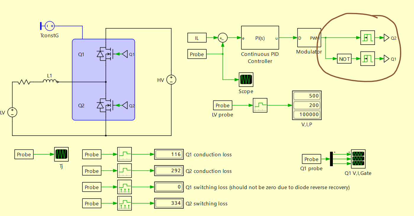
One solution is to make the dead-time zero, because the converter will still run in PLECS this way, but the diode conduction losses won't be accounted for, which is an important part of the analysis that I am doing. I am not very comfortable with your solution, because it will make the timestep very small and slow down the simulation. It is not a very robust solution in my opinion.
The way PLECS computes reverse recovery losses in its MOSFET model with the integrated diode is it check for the application of a reverse bias voltage at the time the diode current cuts off forcibly to compute the reverse recovery loss instead of relying on the gate signal.
Would you be able to implement something like this with your custom component and XML? Using this component (FET/IGBT + Diode), I have never faced any issues with missing reverse recovery losses in the past.
0 -
Hi Prathik,
Thank you for your detailed feedback on our models. I had clearly not realized the depth of this issue!
To be frank I can't quite identify why the customized model (WolfspeedMOSFET) I provided to you is not correctly calculating the reverse recovery losses. I plan on reaching out to Plexim for some help.However, having taken a step back to consider the options, I felt a better solution for your request would be to ditch the custom model entirely and build a new set of models which are formatted to use the built in "MOSFET with Diode" model in PLECS. To be honest, until testing it this week, I didn't realize you could create a model of this type with both gate on and gated off conduction losses.
Using this model, the reverse recovery losses are now correct for deadtime:
As well as asynchronous switching:
Here is the updated simulation file I have been using:
I think these new models will resolve this issue in general, but don't hesitate to let me know if you see any other problems!
Thanks for choosing to work with Wolfspeed!
Blake0 -
Hi Blake,
For some reason, PLEXIM has programmed the MOSFET+Diode component with the gate dependent conduction loss disabled by default, and it is not even intuitive to discover that option. I have been using PLECS for nearly 4 years, but I discovered this feature very recently!
Anyways, I just remembered using a custom PLECS MOSFET from Onsemi sometime last year, which I downloaded from their website, and it is pretty similar to what you are trying to develop. I do not remember facing any issues with this model and have attached it below for you to reverse engineer and see if it helps you in any way with your development.
Thank you for your timely and honest responses. It helps me a lot.
Prathik.
0