
SpeedFit™ Design Simulator
Simulate and evaluate the performance of SiC-based power circuits and determine the right SiC device in seconds.
Start a SimulationLosses Estimation Details

I would like to understand a bit more in detail how the SpeedFit Simulator estimates losses. Which graphs from the component datasheet are exactly used and how the calculation is executed. About the body diode, are reverse recovery losses considered? Any clarification and additional information provided on these aspects it would be helpful, thanks.
Comments
-
Thank you for your post, it has been approved and we will respond as soon as possible.
0 -
Hi constas,
SpeedFit uses the same loss values as our offline PLECS models, which you are welcome to take a look at if you'd like to see more specifics on the values in the tables (https://www.wolfspeed.com/tools-and-support/power/ltspice-and-plecs-models/).
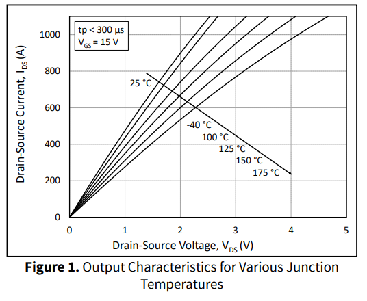
In general, the conduction losses are calculated from the output characteristics:
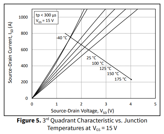
3rd Quadrant Characteristic vs. Junction Temperature at VGS = 15 V:
And body diode:
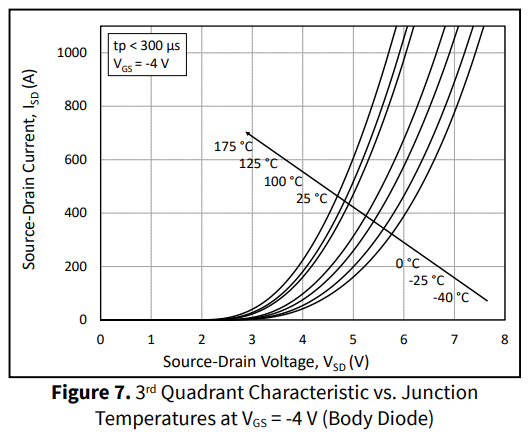
The specific table used depends on the state of the gate and direction of current.
As for switching losses, as of August 2025, SpeedFit calculates the turn-on and turn-off losses, but not the reverse recovery losses.
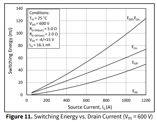
Typically, reverse recovery losses represent a very small percentage of total switching losses, but to improve the accuracy of our simulation we are currently working on an upgrade to SpeedFit that would include reverse recovery losses. Unfortunately I can't give you a firm date on the completion of that upgrade at this time.
Of course, another very important part of the SpeedFit simulation is the thermal model, which is based on the transient thermal impedance:
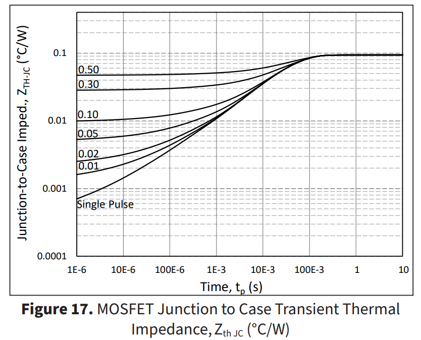
SpeedFit represents the thermal models with a cauer network fit to the Zth data, and you can find the specific values in our PLECS models. We also have a spreadsheet with RC thermal networks of all our module products in this download:
Is there any other part of the SpeedFit simulation you would like more information on?
Thanks,
Blake0