
SpeedFit™ Design Simulator
Simulate and evaluate the performance of SiC-based power circuits and determine the right SiC device in seconds.
Start a SimulationWolfspeed's 60kW DAB unit

Hi,
I am interested in DAB for the DC fast charger. Hence I have seen Wolfspeed's 60kW DAB unit . Its quite interesting to go through the module. Few points on that.
1)Is the unit available in market? If yes where I can get it. If no, when it will come with and with what all details (whether it includes firmware also?)
2)How is the liquid cooling done in the module, did not find more details.
3)Its confusing that you have used CBB011M12GM4-Full Bridge Module in schematic and CAB006A12GM3-Half-Bridge Module in the documentation pdf. Which is the one in the tested module.
4)On what extent the protections, fault circuits are tested as per the schematic. Did the real hardware of the module is fully functional for 60kW?
5)Please provide details on transformer and inductors used. Are they planar ones or wire wound ones?
6)Did the prototype is tested for lower output voltages like 400V? This can increase the current flowing through the switches during a 60kW opoeration since the modulation scheme chosen is single phase shift. Hence I think the components needs to be modified to withstand such high current.
Please share your thoughts and feedbacks on these points or aspects. Awaiting for your support.
regards,
Vishnu
Comments
-
Thank you for your post, it has been approved and we will respond as soon as possible.
0 -
Hello Vishnu,
Thank you for your interest in this product. I answered each of your questions individually below.
1. This unit is not available for purchase. We do not plan to release it to production, though we are actively working on a user guide and additional documentation about the design. All the design files are already available on the web found here. At this time, we are not planning on providing firmware support.
2. The modules are mounted to a custom cold plate with several cooling pins. I provided rendering pictures of the cold plate below showing the custom cooling pins. The pins follow the same spacing and geometry as Wolfspeed's YM series of power modules.
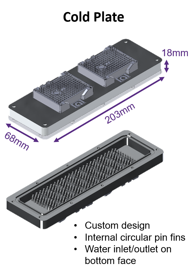
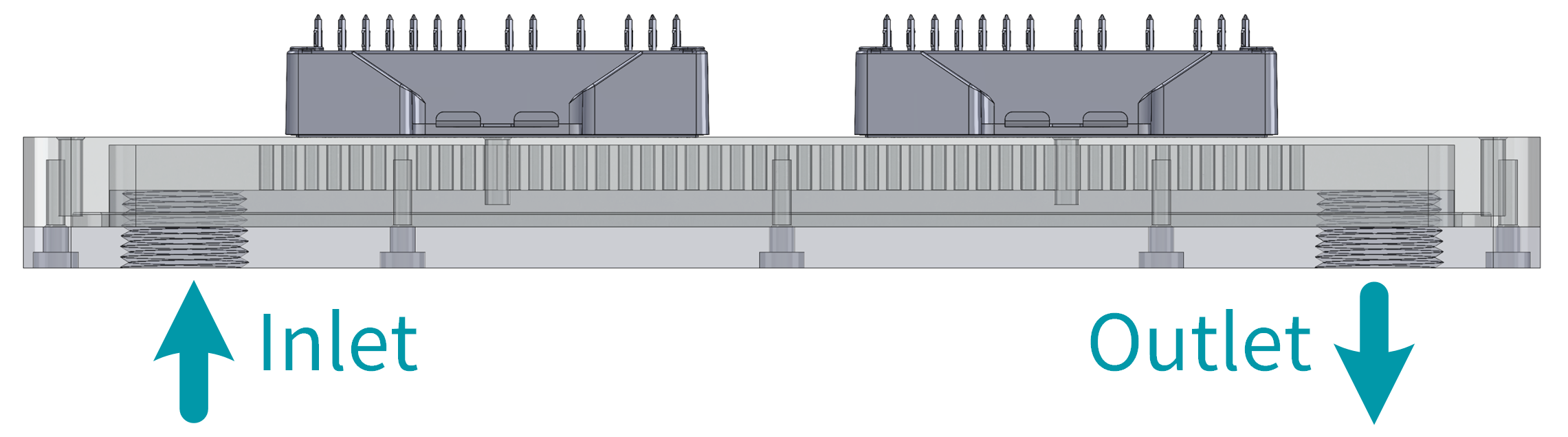
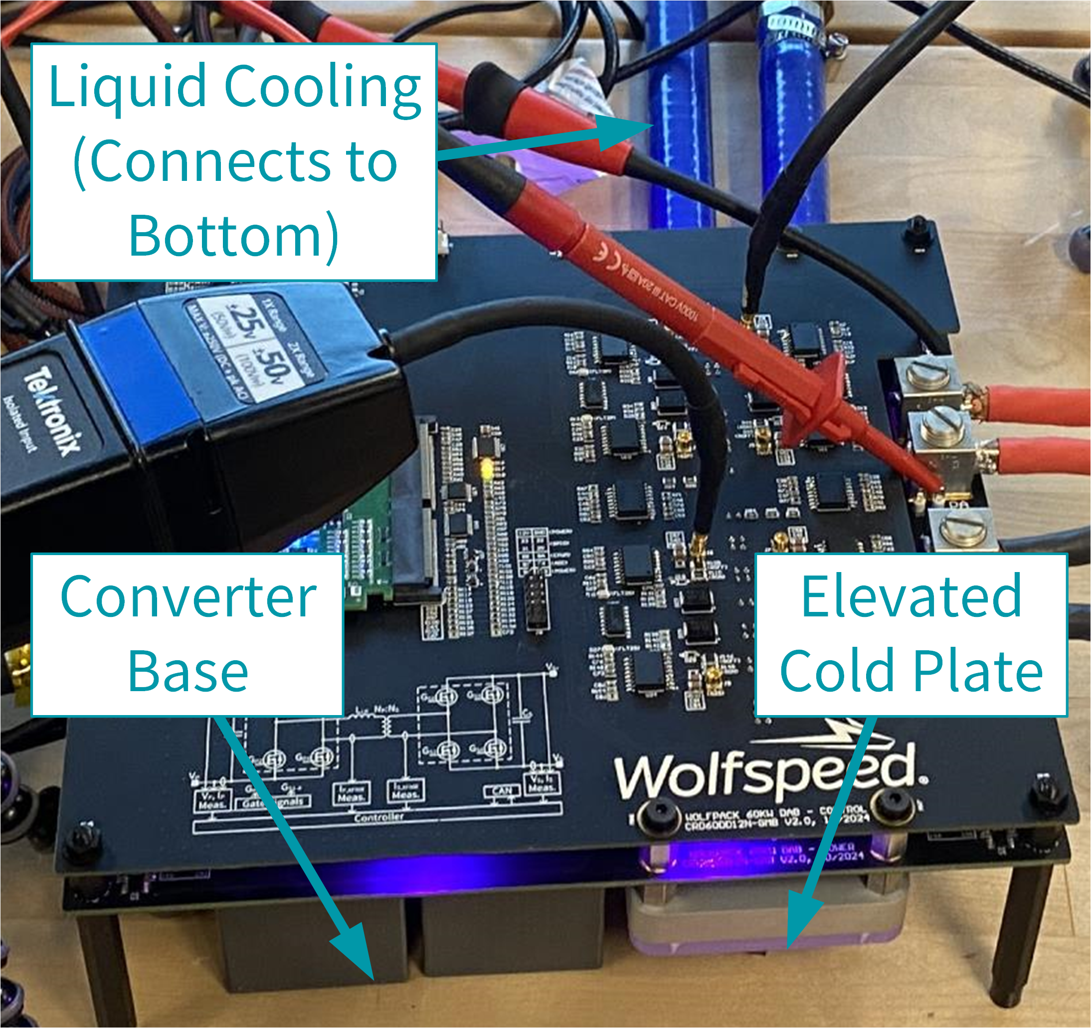
The cold plate is elevated compared to the bottom of the converter (i.e. the bottom of the bulk capacitors), so the liquid cooling lines attach to the bottom of the cold plate. This is shown in the notional figure and the experimental setup shown below.
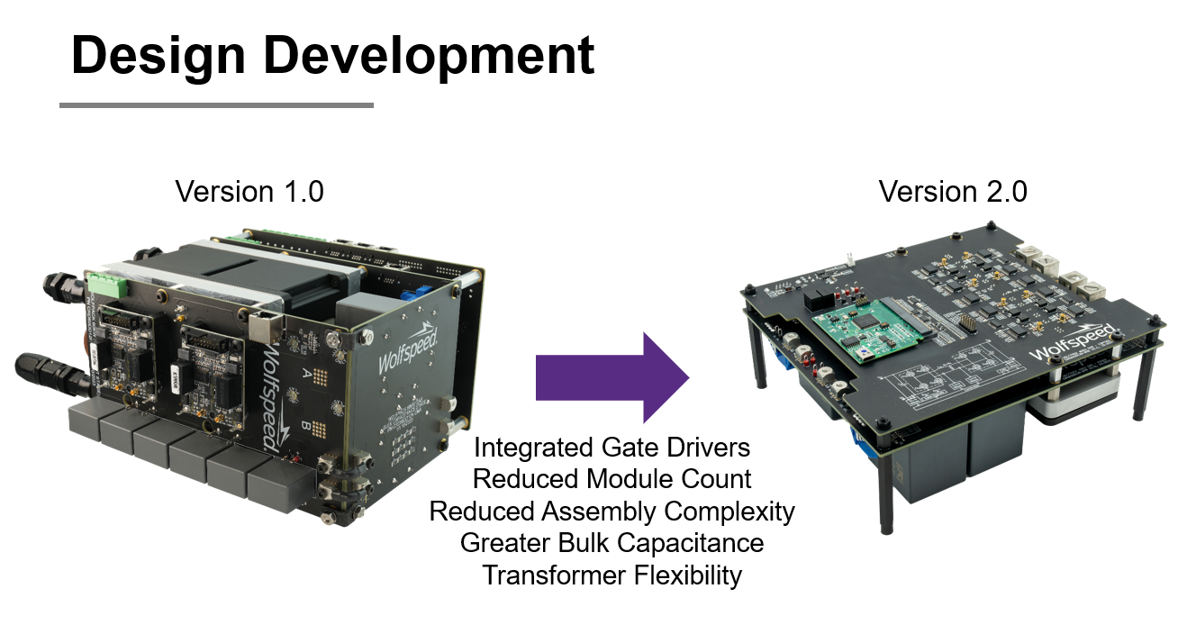
3. This design (CRD60DD12N-GMB) uses two CBB011M12GM4T full-bridge power modules, one on the primary side and one on the secondary side. A legacy version of the design (CRD60DD12N-GMA) used CAB006A12GM3T half-bridge power modules, two on the primary side and two on the secondary side. More information about the legacy design can be found here, and I provided comparison pictures of the design iterations below. We upgraded to the CBB011M12GM4T when Wolfspeed's Generation 4 MOSFETs were released, since it allowed the design to be shrunk due to the better switching performance of the new devices. All testing of the CRD60DD12N-GMB has been performed with CBB011M12GM4T full-bridge power modules.
4. The hardware was experimentally tested up to its rated 60 kW. The only fault circuitry included in the testing was the overcurrent protection in the form of a DESAT circuit.
5. This design uses the leakage inductance of the transformer for achieving zero voltage switching (ZVS). No separate inductor was needed for testing. The transformer is wire wound. It was a custom solution that we wound internally with a magnetizing inductance of ~100 µH and a leakage inductance of ~5 µH. It used Ferroxcube E100/60/28-3C94 ferrite E cores with AWG4-equivalent Litz wire. We’ve been working with our magnetics partners to develop a transformer solution for public release.
6. Our initial testing was performed at 800 Vout, though we have more testing planned. I agree with you that the design requires more current to support lower voltages. This board is designed to operate at full power down to 700 V and can operate down to 400 V at de-rated power.
Thanks,
Chris N.
0 -
Hello Vishnu,
I hope that answered your question. I will close this discussion for now but if you have a follow up question, please "Start a New Discussion" and we would be glad to support you further.
Thanks,
Chris N.
0