
SpeedFit™ Design Simulator
Simulate and evaluate the performance of SiC-based power circuits and determine the right SiC device in seconds.
Start a SimulationLTSpice Model troubles...

Hello everybody.
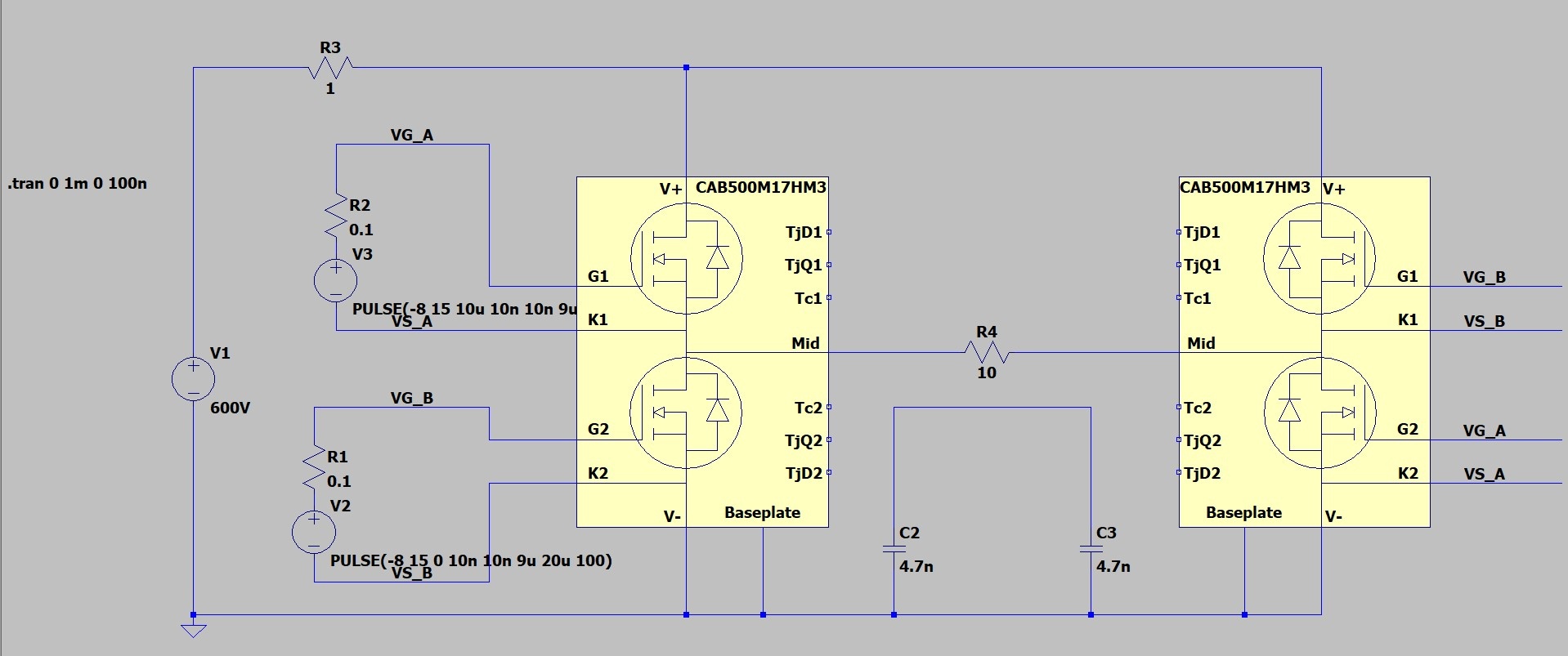
I'm trying to simulate the circuit you can see in the picture.
From the simulation results with LTSpice it seems that the hi-side MOS doesn't switch well, most of the 600V drops across the D-S junction.
As you can see, I'm driving with -8/+15V with a 50kHz frequency.
The model is the one available in the Spice tool, so I'm confident that is correct.
Could you kindly give me some suggestions about this misfunctioning?
Thank you very much!
Comments
-
Thank you for your post, it has been approved and we will respond as soon as possible.
0 -
Hi Paolo,
Having recreated your circuit, I believe I have identified the core issue: your current design is linking K1 of the right module to K2 of the left module, which leads to some unexpected behavior (basically an unintended short circuit). I altered the schematic to look like this by adding additional gate drives:
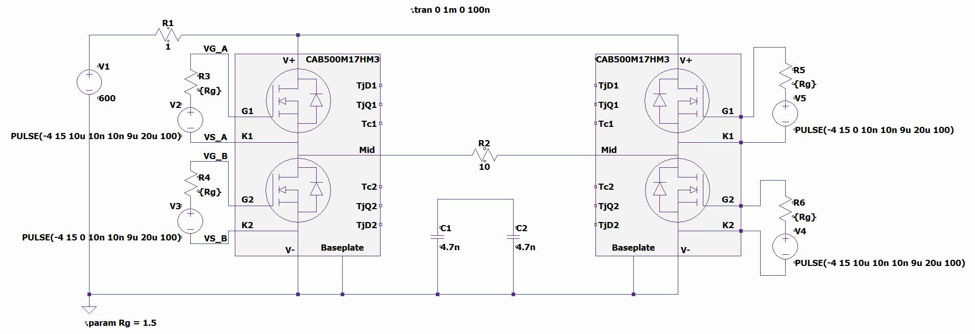
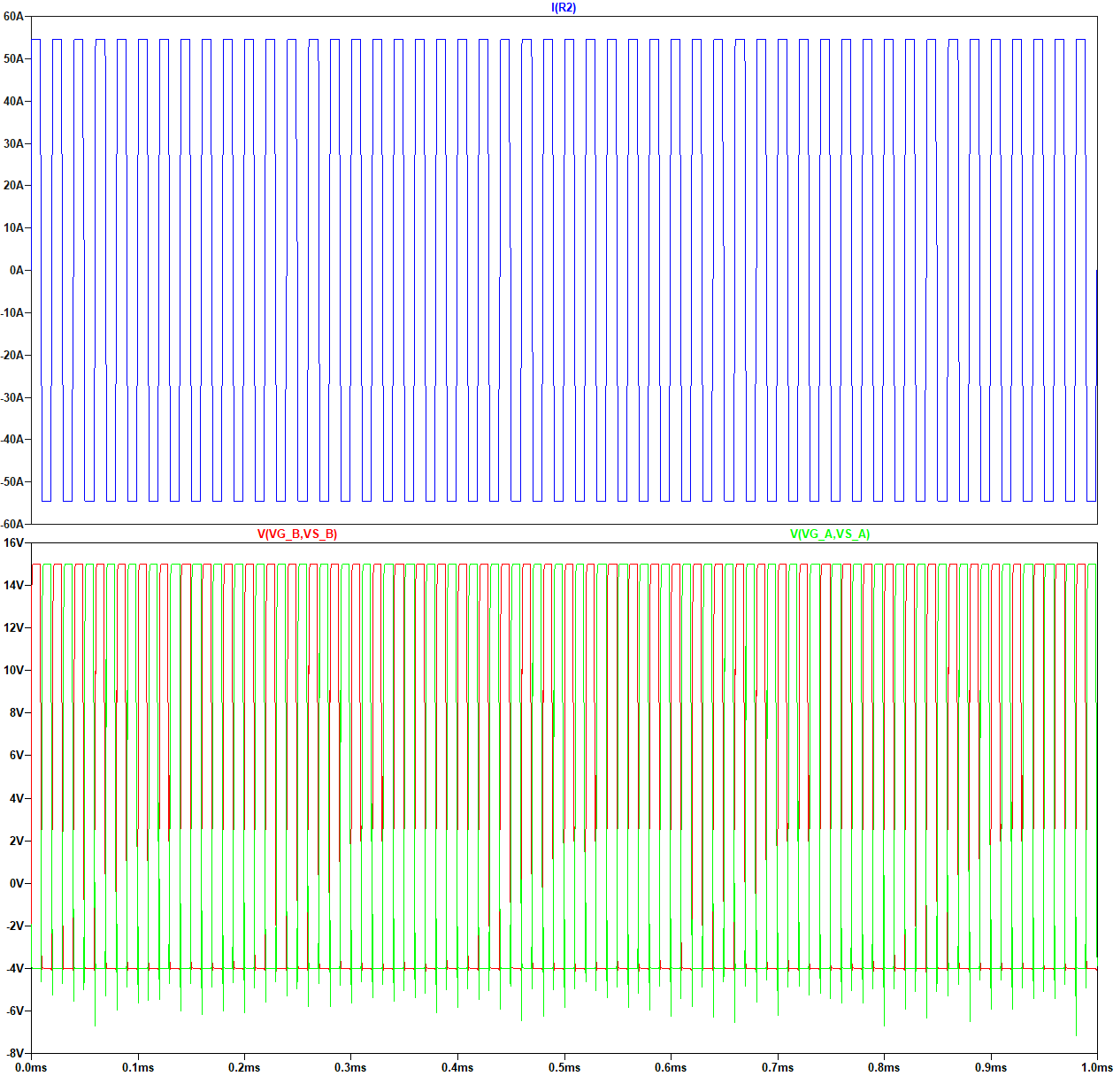
And I was able to get much better results.
Additionally, I update the gate resistance and negative gate bias to match the datasheet, as that would always be our recommendation, but you are of course welcome to simulate conditions outside of safe operation. An Rg of 0.1 Ω is unlikely to be an issue at 600V bus (Vds,max is unlikely to violated during switching), but operating at -8V on the gate will lead to exiting gate voltage safe operating area during switching.
Here is my model file if you would like to use it:
Please let me know if this resolves your issue, and if you have any additional questions!
Thanks,
Blake0