
SpeedFit™ Design Simulator
Simulate and evaluate the performance of SiC-based power circuits and determine the right SiC device in seconds.
Start a SimulationFeasibility of 0.01 K/W Case-to-Heatsink Thermal Resistance with Baseplate-less Wolfspeed Modules

Dear Team,
We are currently working on thermal modelling for a high-power SST application using Wolfspeed SiC power modules, specifically: CAB5R0A23GM4 and CAB004A12GM4
These are baseplate-less modules, so we are trying to understand the practical thermal interface limits between the module case and the liquid-cooled heatsink/cold plate.
Our target assumption in the thermal model is:
Rth case-to-heatsink = 0.01 K/W
My doubt is whether this value is realistically achievable for baseplate-less devices like the above modules, considering practical factors such as:
- Thermal interface material thickness and conductivity
- Mounting pressure / clamping force
- Cold plate flatness and surface finish
- Module footprint and heat-spreading limitations
- Long-term reliability under thermal cycling
Could you please clarify whether 0.01 K/W case-to-heatsink thermal resistance is a realistic design target for these modules, or if a higher value should be used for practical thermal modelling?
Any recommended thermal interface material, mounting guideline, or typical Rth case-to-heatsink range for these modules would be very helpful.
Thank you.
~Anusha D
Comments
-
Thank you for your post, it has been approved and we will respond as soon as possible.
0 -
Hello Anusha,
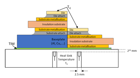
It is the industry standard to measure baseplate-less modules Rth junction-to-heatsink, so the Rth case-to-heatsink that you are concerned with is included in this value. Rth JHS includes the thermal stack of the module, the TIM layer and 2 mm of aluminum (heatsink). This is the value that we report on the datasheet.
You are correct that the 5 factors you listed will impact the actual Rth case-to-heatsink or Rth TIM. Other factors will include total die area and DBC layout/material, which relate to your #4 factor of heat spreading limitations. It is difficult to accurately quantify the value you are inquiring about with baseplate-less modules through empirical measurement, which is why the industry standard is to measure Rth JHS.
If possible, my recommendation is to not model Rth CHS separately but use the Rth JHS value provided in the datasheet and model the rest of the system. If you are using comprehensive thermal models, you can model the TIM layer by giving it an approximate thickness of 50 µm and using the thermal conductivity stated on the datasheet. This thickness may need to be adjusted because different TIM material can result in different bond line thicknesses, and different contact thermal resistances.
We recommend using PTM6000HV-SP, a PCM TIM developed by Honeywell. This is the pre-applied TIM material that we use for our Wolfpack modules, including the CAB5R0A23GM4T and CAB004A12GM4T. It is the TIM material used when reporting Rth JHS on our datasheets. We offer modules with the TIM pre-applied to simplify processing and procurement on the user end. I’ve linked our WolfPACK Mounting Instructions and PCB Requirements user guide and Thermal Characterization Methods and Applications application note for your reference.
Best regards,
Dustin Hill
0