
SpeedFit™ Design Simulator
Simulate and evaluate the performance of SiC-based power circuits and determine the right SiC device in seconds.
Start a SimulationInteraction of CHAN and ADC modules - problems with noise in measurements

Dear Sir or Madam,
For the needs of one of our projects in the previous period, we ordered an inverter Wolfspeed-CRD300DA12E-XM3. So far, the inverter has served us really well and has had very nice behavior.
We currently have a problem that manifests itself on the digital measurement channels (ADC inputs) when the CAN modules are working, so please advise us on what we can do.
In order to clarify the problem, I am providing several experimental results in the attachment.
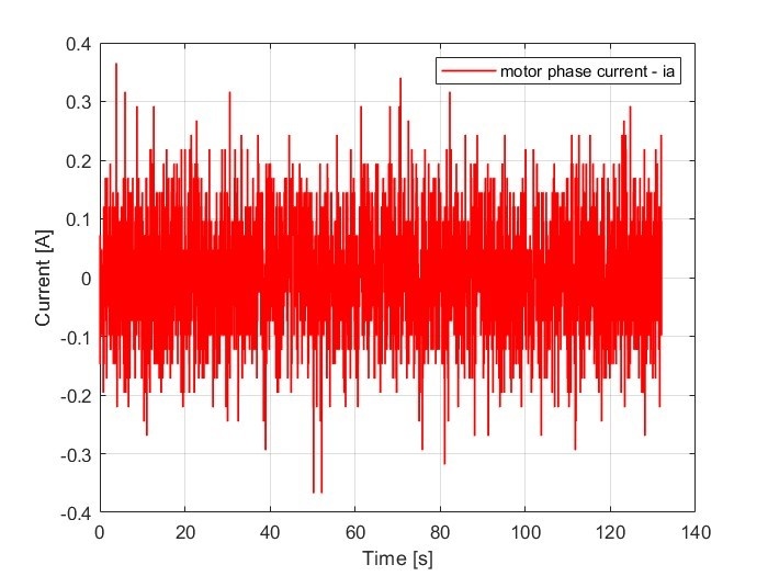
All of the above tests were conducted without voltage on the DC link, and without power, the inverter power stage was not switching. The auxiliary electronics was powering the drivers and sensors. The sampling frequency is 400 kHz. Eight consecutive samples are averaged to reduce oscillations noise (i.e. oversampling is applied). When no CAN module is running, the measurements look like shown in Figure 1.
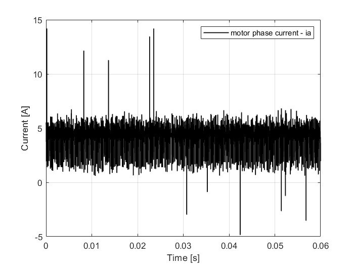
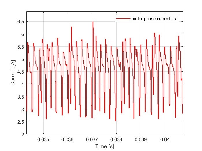
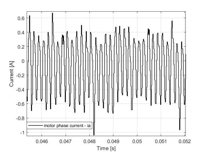
When there is communication via the CAN_A module, large spikes occur in current measurements, as shown in Figure 2. A more detailed depiction of the phenomenon can be seen in Figure 3. Offset is not a problem and is eliminated when there is voltage on the DC link. However, faster oscillations and high-power spurious spikes mean that we cannot use an inverter for our application.
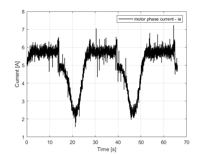
When the CAN module B is turned on, very slow dips in the measured current occur, which are shown in Figure 4. These dips without oversampling go up to 15A. Also here, faster oscillations occur exactly at the communication (CAN) operating frequency of 5 kHz, as shown in Figure 5.
Is there any known problem with the inverter design or its interaction with the TI board and do you have any advice on how to overcome these problems?
I would like to mention that I have seen similar phenomena with another of your clients at the link :
Thank you very much for your time and help.
Best regards,
Aleksandar
Comments
-
Thank you for your post, it has been approved and we will respond as soon as possible.
0 -
Hello Aleksandar,
We've already had some offline communications together regarding this challenge, but I wanted to document some of the recommendations. A lot of testing has been performed on this inverter both by Wolfspeed and our customers. We haven't observed this issue previously, but we certainly want to get it resolved and ensure others don't experience this same challenge. I listed some of the potential troubleshooting steps below.
- Higher Power : The current sensors and corresponding feedback circuits are optimized to capture the full dynamic range of this reference design (several hundred amperes). At low currents, the feedback signal is very small and therefore has a very low signal-to-noise ratio (SNR). Try operating the reference design at higher power levels (closer to its ratings) to ensure a better SNR.
- Modify Current Sensor Conditioning : If the system is expected to operate at lower power levels consistently, consider changing the current sensors and/or current feedback circuits to be optimized for lower currents to ensure an improved SNR at the lower power levels.
- Isolated CAN : Consider using an isolated CAN adapter for communicating with the design such as the PEAK System PCAN-USB Pro FD to reduce noise coupling opportunities.
- Reduce CAN Frequency : Operating the Controller Area Network (CAN) communication at a lower frequency could reduce the noise coupling and at a minimum would reduce the regularity of the noise.
- Filtering Elements : Increase the decoupling capacitors near the CAN transceiver to further minimize voltage rail spikes. Consider adding a common mode (CM) choke on the CAN wires to the control board or on the control board itself. Consider adding small filtering capacitors to the CAN signals.
- Segment CAN : As Jonathan mentioned in the response to the forum post that you identified, the traces for the current measurement are far from the CAN signals, so it is surprising to observe significant coupling between them. To further reduce any influence, you could consider disconnecting the CAN signals from the Texas Instruments (TI) controller by removing pins or modifying traces and connecting communications directly to the TI controller. This would demonstrate if this coupling is due to the board layout or another cause. You can also consider using unused pins on the controller to adopt other communication protocols.
- Scrutinize Interrupt Levels and ADC Timings : CAN communication triggers an interrupt in the TI controller. Review when this interrupt occurs to see if it is interfering with the analog-to-digital (ADC) measurement or other systems causing a spike. Similarly, review the ADC configuration settings to ensure the sample windows make sense for the measurements and CPU resources.
Thanks,
Chris N.
0 -
Hi, I hope that this answered your question. I will close this discussion for now but if you have a follow up question, please "Start a New Discussion" and we would be glad to support you further.
0