
SpeedFit™ Design Simulator
Simulate and evaluate the performance of SiC-based power circuits and determine the right SiC device in seconds.
Start a SimulationSuitability of using gate drive booster to drive MOSFET modules

Hello,
I am going to use the CAB6R0A23GM4T SiC MOSFET power module in a high voltage, multilevel converter design. In order to minimize the switching losses, I would like to try to use zero external gate resistance in my circuit. For a drive voltage of +15V/-4V, the theoretical maximum peak current (assuming that the driver is ideal and there is no inductance between the driver output and the gate of the MOSFET) for zero external gate resistance is (Vhigh - Vlow)/Rgint = (15-(-4))/1.3 = 14.6A.
To achieve this, I initially proposed the use of the UCC5881 gate driver IC, which is capable of sourcing/sinking up to 15A. This part uses an SPI interface for configuration and data readout. However, the custom controller being used in this application does not support SPI and driver IC cannot be used properly.
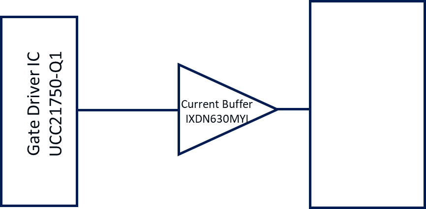
There don't seem to be any gate drivers without SPI and other protection features that have such a high gate drive strength, and the driver IC with the closest drive strength having all the features that I need is the UCC21750. This part has a maximum drive strength of 10A and won't allow me to even test if it is possible to get close to the theoretical maximum of ~15A. To solve this, I decided to add the IXDN630MYI in series with the UCC21750 to boost the drive strength to 30A.
Although this allows me to test possibility of getting up to ~15A of peak drive current, the gate driver no longer has to ability to initiate soft turn-off in the even of a DESAT fault, which increases the risk of overvoltage breakdown due to very fast turnoff.
I would like to understand a couple of things:
- How serious is the risk of overvoltage breakdown due to the loss of soft turn off, even if the board layout is good with low stray inductance?
- Are there any ways of mitigating overvoltage breakdown in such a setup without implementing a discrete soft turn-off solutions?
- Does Wolfspeed have a recommended gate driver IC for this power module?
- Are there any equations that I can use to calculate a more realistic value of the peak gate current taking into account real-world non-idealities such as the rise/fall times of the gate driver, stray inductance, etc? (I know that LTspice simulations will help me find out the realistic maximum drive current, but having and equation to quickly calculate this and back up simulation results helps a lot)
Please let me know what you think.
Regards,
Prathik.
Comments
-
Thank you for your post, it has been approved and we will respond as soon as possible.
0 -
Hello Prathik,
In low-inductance circuits, the Wolfspeed CAB6R0A23GM4T is capable of operating reliably with RG(EXT) = 0 Ω. This is the gate resistance value employed to create many of the datasheet plots. Please note that a gate drive IC or buffer stage also includes output resistance, which reduces the circuit's peak current driving capability since this resistance is in series with the module internal resistance. Many gate drive ICs add ~0.3-0.5 Ω of additional resistance. This must be considered when determining peak output current.
We typically observe 10 A of peak drive capability being suitable for this power module (when not paralleled), though we recognize that there can be other potential benefits of adding a buffer stage besides increasing the output current such adding the buffer closer to the power module and/or reducing the gate driver IC output resistance. Our partner, Texas Instruments, released an evaluation board for Wolfspeed parts which includes an output buffer stage (UCC2189X5YQEVM-096). I recommend reviewing those design files as a reference, since that design still has soft turn-off functionality. I answered your specific questions below.
- It is always important to have low stray inductance in the power and gate loops. This will enable faster switching speeds and reduce overshoot/ringing. As you indicated, it is also critical during turn-off after short circuit events. We recommend keeping soft turn-off functionality to ensure that you keep the device within its safe operating area. In this response, I included some example ways to maintain soft turn-off functionality even with an output buffer stage. If it is unfeasible for you to have a soft turn-off implementation, we can get an NDA in place to discuss your specific operating conditions and the risk of voltage breakdown in those conditions.
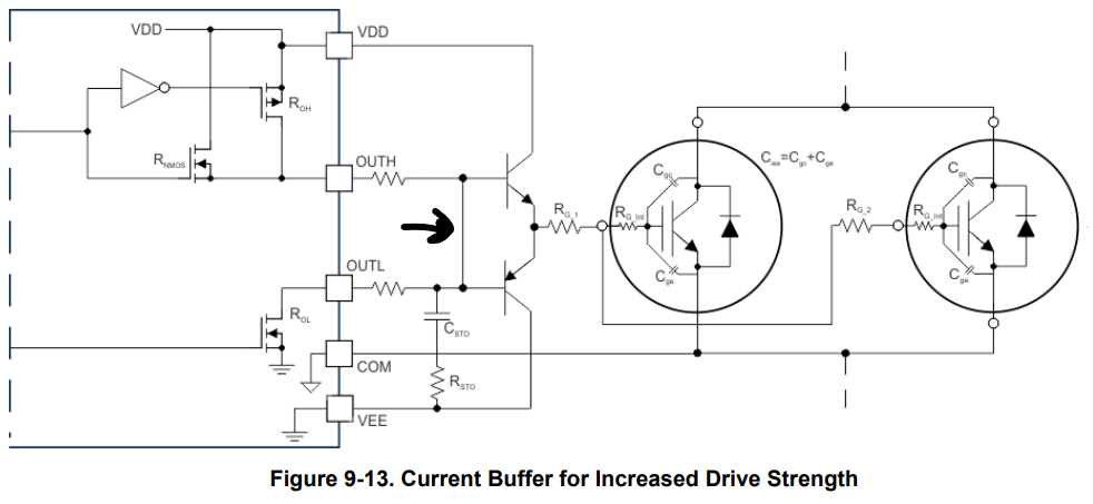
- In Section 9.2.2.8 of the UCC21750 datasheet, Texas Instruments includes information on achieving soft turn off when using an external current buffer. I recommend you refer to that section.
- Wolfspeed uses the Texas Instruments UCC21710 for a lot of internal testing with this module. It has a working voltage up to 2121 VDC. It is similar to the UCC21750 that you are already considering.
- Unfortunately, I do not know of any simple equations for estimating the peak gate current. The capacitances of the MOSFET are non-linear which makes it difficult to estimate the peak current without making large simplifying assumptions. The challenge is further obfuscated by the influence of parasitic elements. We recommend using LTspice for a more accurate estimation. The power module model is built into LTspice directly by navigating to Place Component > Contrib > Wolfspeed > Halfbridge > CAB6R0A23GM4. Wolfspeed also provides the models for download here. In that same download link, Wolfspeed provides the template simulation DPT_Test_Stand_HB.asc. You could use the .step command in LTspice to sweep a variety of operating conditions and observe the resulting peak gate current.
Thanks,
Chris N.
0 -
Hi Chris,
Thank you for your response. I do understand that the driver output resistance and the circuit inductance does limit the peak gate current below the theoretical maximum of 15A and was just using that as a reference value to select a driver IC.
From Wolfspeed's tests using the UCC21710, what was the maximum gate current measured with zero external gate resistance? Did it ever reach a high peak of >10A? And in your opinion, does it make a lot of sense to add an external buffer if it does not significantly improve the drive strength of a 10A driver alone? Although adding a buffer increases the drive strength, it is not really desirable for us if the benefit is not too significant because it is an extra component on the board. Moreover, additional components are necessary to achieve STO.
Thanks,
Prathik
0 -
Hello Prathik,
I encourage you to evaluate your operating conditions in an LTspice simulation. Wolfspeed has spent considerable time to tune and validate our models, so this should be your best tool for predicting performance in your setup. Gate current is not a typical time-domain measurement that we record during our extensive sweep of various operating conditions.
A drive strength of 10 A should be fine for most applications with this module (when the modules are not paralleled). We typically observe a larger impact due to the internal resistance of the gate driver IC rather than the maximum gate driver current rating. Please note that it is critical that regardless of the gate driver employed, the driver needs to have a low gate loop inductance. Please see PRD-09301 for more details about best practices for gate loop routing.
Thanks,
Chris N.
0 -
Hi Chris,
From the LTspice simulation, with a capable driver and low stray inductance, I see that it is possible to achieve 10A-12A of peak current. Based on what you said in your first response, I think its best to use the totempole buffer recommended by TI in section 9.2.2.8 of the UCC21750 datasheet to be able to achieve the peak current of 12A. In addition to this, they have shown a very simple way to achieve STO just by adding an RC circuit.
One thing that I noticed (see screenshot below) is that they are bridging the OUTH and OUTL pins of the driver, which I think would affect (slow down) the turn on speed because the STO RC circuit will slow down the rise time of the pin. The RC STO circuit should only slow down the turn off, if I understand correctly, so shouldn't the OUTH and OUTL pins be connected separately to the NPN and PNP transistors? Please let me know what you think and correct me if I am wrong.
 0
0 -
Prathik,
The key difference is that the soft-turnoff (STO) feature is limited to 400 mA whereas the UCC21750 operates with the full 10 A drive strength during normal operation. During a soft-turnoff event, the low STO current makes the STO capacitor, C_STO, more impactful. When the system is operating normally, C_STO is charged/discharged at least an order of magnitude faster. It still introduces a small delay in normal turn-on/turn-off dynamics, however this delay will be significantly shorter and should be approximately consistent for both turn on and turn off.
Thanks,
Chris N.
0 -
Thanks Chris!
I have one last question. Do you have a recommendation on how much the STO time should be for this power module? The soft turn off capacitance is calculated based on the desired STO time using the following formula:

Regards,
Prathik
0 -
Hello Prathik,
The soft-turnoff (STO) timing is dependent on the inductance in your system. Ideally, you would shut off the device as fast as possible while remaining in the device's safe operating area (SOA). In high-inductance systems however, you are forced to increase the STO time to still maintain SOA. We recommend a STO timing of 300-400 ns in most applications.
Thanks,
Chris N.
0 -
Hello Prathik,
I hope that this answered your question. I will close this discussion for now but if you have a follow up question, please "Start a New Discussion" and we would be glad to support you further.
Thanks,
Chris N.
0