
SpeedFit™ Design Simulator
Simulate and evaluate the performance of SiC-based power circuits and determine the right SiC device in seconds.
Start a SimulationSchematic Diagram of CGD1700HB3P-HM3

Hello, I have purchased the CGD1700HB3P-HM3, but I have some questions regarding its schematic diagram. Could you please clarify which specific components in the schematic diagram correspond to Rgic-on, Rgic-off, Rg(ext)(on), and Rg(ext)(off) respectively as stated in the data sheet?
Looking forward to your reply. Thank you very much.
Comments
-
Thank you for your post, it has been approved and we will respond as soon as possible.
0 -
Hello Emma,
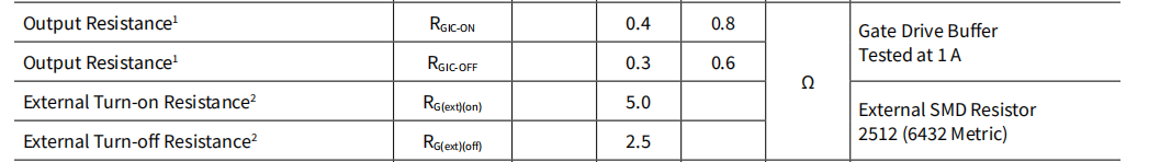
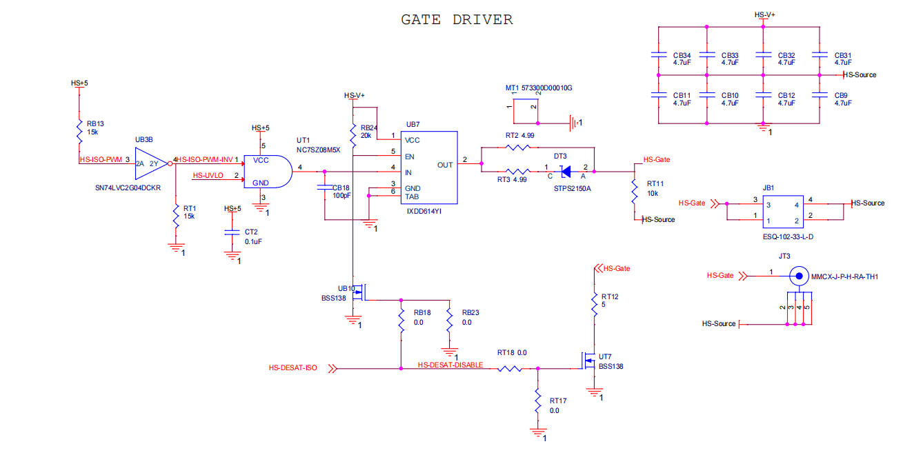
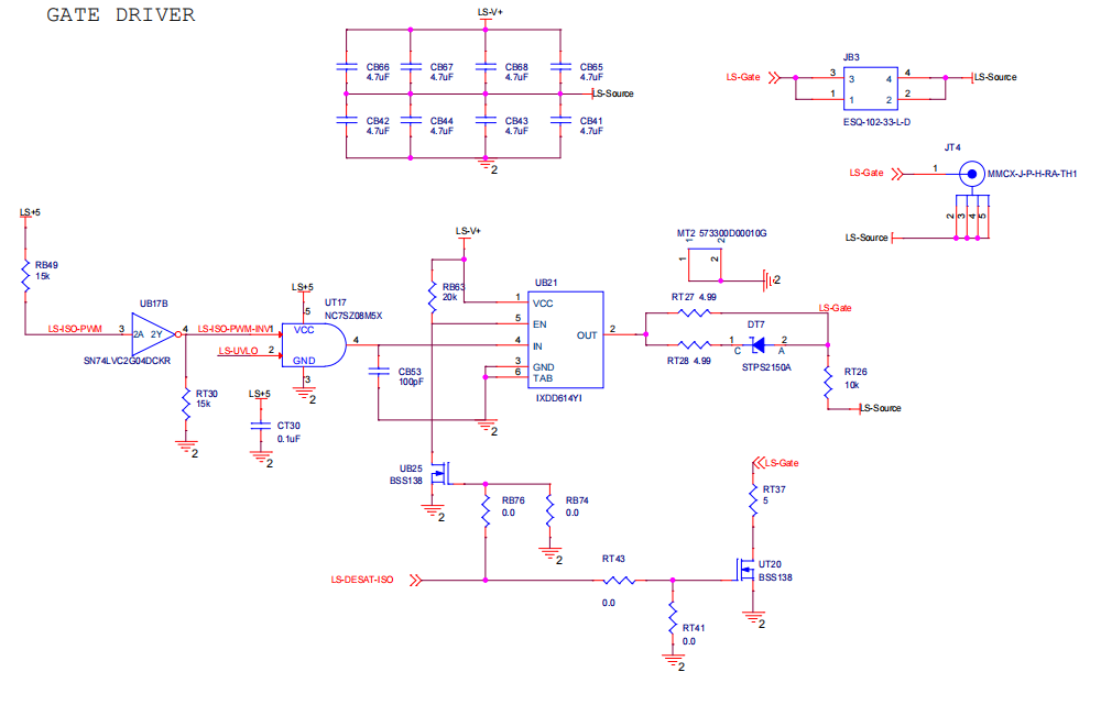
Rgic-on and Rgic-off are the internal turn-on and turn-off resistances, respectively, of the gate driver integrated circuit (IC). These ICs are reference designators UB7 for the high side and UB21 for the low side. The datasheet for the gate driver IC (IXYS IXDD614YI) gives more information about these values.
The turn-on gate resistance, Rg(ext)(on), comes from reference designators RT2 (5 Ω) for the high-side and RT27 (5 Ω) for the low-side. The turn-off gate resistance, Rg(ext)(off), is the parallel combination of gate resistors. For the high side, its RT2 || RT3 = 5 Ω || 5 Ω = 2.5 Ω, and for the low side its RT27 || RT28 = 5 Ω || 5 Ω = 2.5 Ω. The gate driver uses steering diodes so that RT2 and RT27 are used for both turn-on and turn-off dynamics, whereas RT3 and RT28 are only used for turn-off dynamics. This allows for independent tuning of turn-on and turn-off switching dynamics. More information about the steering diodes and independent tuning is provided in Section 3.2 of PRD-09301.
Thanks,
Chris N.
0 -
Hello Emma,
I hope that this answered your question. I will close this discussion for now but if you have a follow up question, please "Start a New Discussion" and we would be glad to support you further.
Thanks,
Chris N.
0