
SpeedFit™ Design Simulator
Simulate and evaluate the performance of SiC-based power circuits and determine the right SiC device in seconds.
Start a SimulationCRD25DA12N-FMC-AFE: Difficulty running a purely electrical simulation in PLECS

Hello everyone,
I am an engineering student currently working on an academic project involving the 25 kW Bi-Directional Three-Phase Inverter (CRD25DA12N-FMC-AFE).
I am using the PLECS models provided for this reference design to analyze the system's behavior. However, I am struggling to perform a purely electrical simulation.
The Issue: The provided simulation models appear to be strictly electro-thermal. I am trying to focus solely on the electrical control loops at this stage, but I cannot seem to decouple the thermal domain. When I try to run the simulation without the full thermal setup, I encounter errors, or the complexity of the thermal calculation slows down my iteration process significantly.
What I have tried: I have carefully reviewed the downloadable design files and documentation (User Guide & Reference Design package), but I was unable to locate a standalone electrical model or instructions on how to disable the thermal calculations in the existing model.
My Questions:
- Is there a simplified, electrical-only PLECS model available for this specific AFE reference design?
- If not, what is the recommended way to "bypass" the thermal domain in the official PLECS model so I can simulate the electrical parameters (Voltage/Current) with ideal (or fixed temperature) conditions?
Any advice or modified simulation files would be greatly appreciated.
Thank you in advance for your help!
Comments
-
Thank you for your post, it has been approved and we will respond as soon as possible.
0 -
Hello JeanVanBeneden,
A few things to note before getting into potential solutions. First, the PLECS simulation available on the web (V1.0) is for the CRD25DA12N-FMC three-phase inverter, not the Active Front End (AFE). It can be modified to support AFE applications, though the default configuration is an open-loop sine pulse-width modulation (SPWM) inverter. Second, Wolfspeed hosts an online tool, SpeedFit, which is built on PLECS and runs directly in a browser with no PLECS license required. The tool includes several topologies, and the simulations are configured to run very fast. You may consider exploring the tool as you are ramping up your simulation efforts. Third, some MOSFET electrical characteristics vary with the MOSFET temperature. In order to get an accurate electrical model, it is important to include the thermal domain. You power loss estimations may have significant error if you are not properly considering the thermals.
Recognizing these limitations, the easiest way to slightly speed up the simulation (when thermal accuracy is not important) is to delete the thermal chains in the "Power Stage" subsystem and place all the devices on a single heat sink, as shown below. In simulations I just ran, this results in approximately a ~4% runtime improvement with all the default model settings.
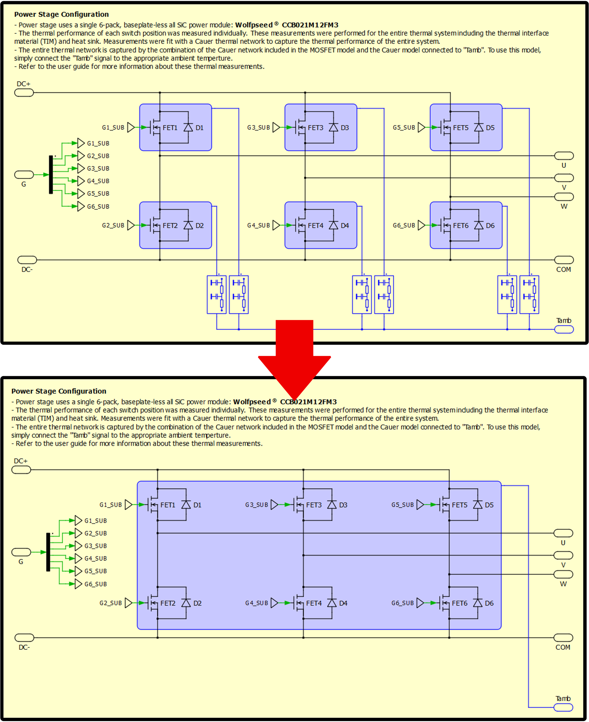
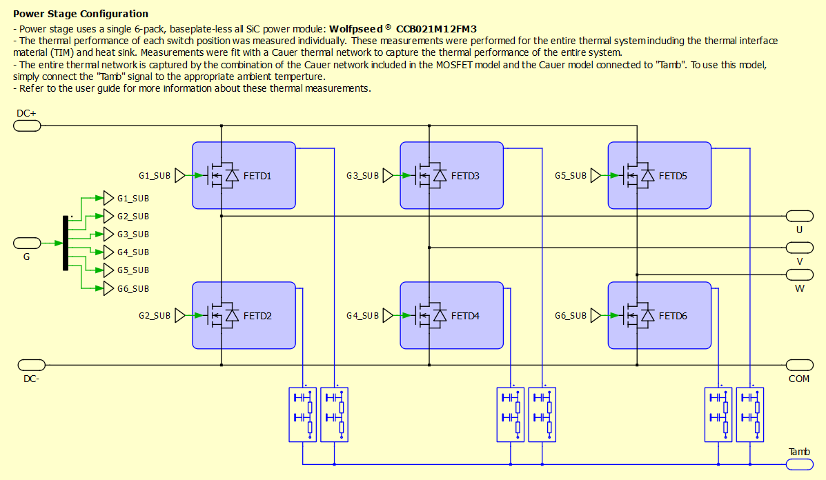
Alternatively, Wolfspeed recently updated the PLECS MOSFET models to include the MOSFET and body diode in the same model element. The CRD25DA12N-FMC PLECS simulation on the web (V1.0) has not yet been updated to take advantage of the combined model. I attached the updated CRD25DA12N-FMC PLECS simulation which uses the updated model. To demonstrate the changes, I provided a picture below of the new "Power Stage" block. This updated simulation (V2.0) should be published soon to the web, replacing the old CRD25DA12N-FMC simulation. In simulations I just ran — before making any changes to the thermals — I observed a ~30% improvement in runtime with this simulation. Transitioning to the updated simulation should help with some of your runtime issues.
Thanks,
Chris N.
0 -
Hello JeanVanBeneden,
The V2.0 simulation (which the combined MOSFET+diode models) is now also available for download directly from the CRD25DA12N-FMC landing page under the Tools & Support tab.
I hope that this answered your question. I will close this discussion for now but if you have a follow up question, please "Start a New Discussion" and we would be glad to support you further.
Thanks,
Chris N.
0