
SpeedFit™ Design Simulator
Simulate and evaluate the performance of SiC-based power circuits and determine the right SiC device in seconds.
Start a SimulationEMI performance of CRD25DA12N-FMC

Hello everyone,
I am designing a three-phase EMI filter on the AC side of a 25 kW FM3 three-phase inverter (CRD25DA12N-FMC).
I am using a proper EMI test setup with LISNs and have already implemented a first passive EMI filter. However, even with relatively large filter components, I am unable to meet the Class B conducted EMI limits.
The main issue appears to be very high common-mode noise. I've tried increasing the common-mode choke and Y-capacitance, but the improvement is still not sufficient.
Has anyone worked with this inverter before or successfully passed Class B limits with it? or any other EMC test ? I would appreciate any insights regarding effective filter topologies, grounding/shielding practices, or known common-mode noise challenges with this platform.
Thanks in advance!
Comments
-
Thank you for your post, it has been approved and we will respond as soon as possible.
0 -
Hello SuyogS,
The inverter is intended to be a starting point for people to get familiar with SiC modules, demonstrate best practices for layout, and start switching immediately during early design-in activities. Because it's used in a variety of laboratory applications, it has not been tested for EMI compliance.
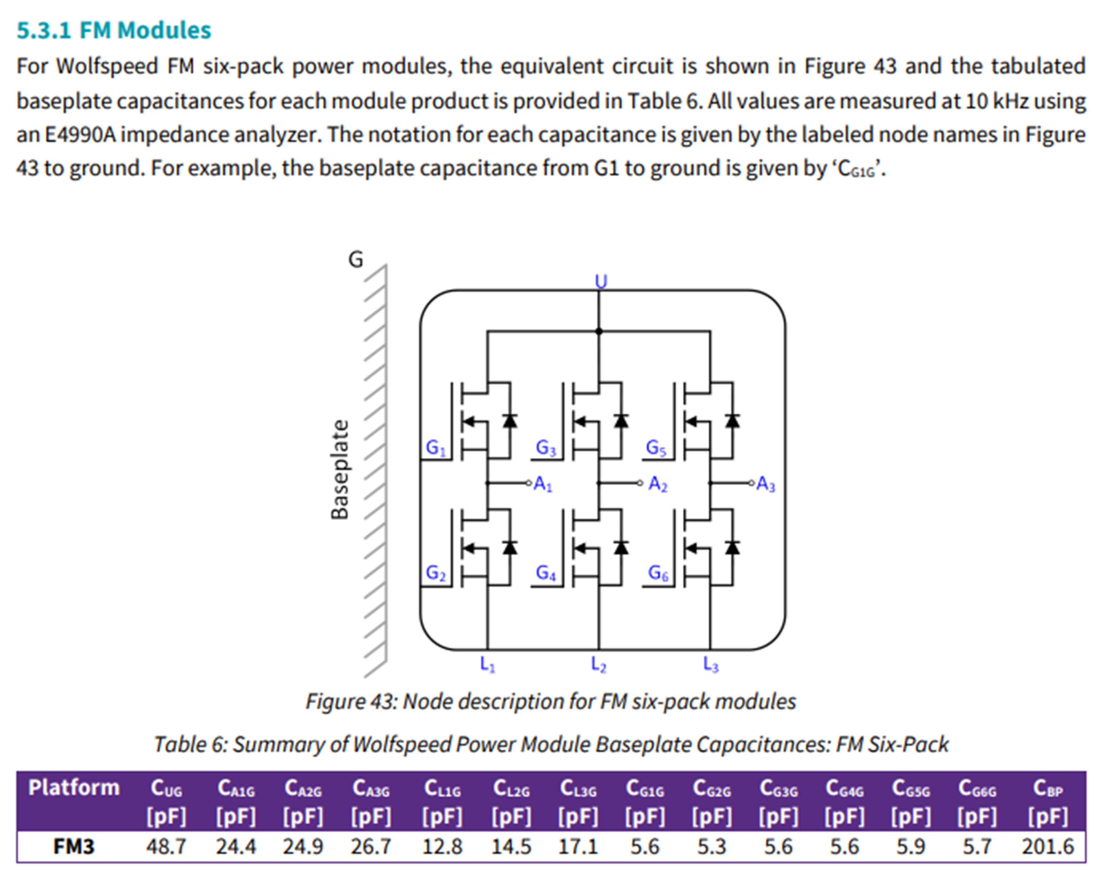
Wolfspeed provides several resources for developing EMI filters for the design though. PRD-07845 includes the measured baseplate capacitances for the FM3 six-pack module used in this reference design (shown below). These values can be used to predict common-mode currents through the baseplate of the module, as detailed in that application note. The baseplate capacitances are also built into the Wolfspeed LTspice models available for download here. Additionally, PRD-08907 steps through the design of an EMI filter for a different Wolfspeed reference design, though the same concepts can be employed for this design.
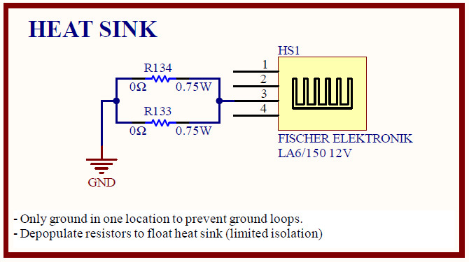
The heat sink of the module is connected to the ground node of the PCB through 0 Ω resistors (shown below). You can consider removing these resistors during testing to float the heat sink. You can also explore implementing PWM dithering to reduce the emissions at the switching frequency and/or reducing slew rates through increasing gate resistance.
Baseplate Capacitances
Float Heat Sink
Thanks,
Chris N.
0 -
Thank you for detailed answers I will try it out.
0 -
Hello SuyogS,
I hope that this answered your question. I will close this discussion for now but if you have a follow up question, please "Start a New Discussion" and we would be glad to support you further.
Thanks,
Chris N.
0