
SpeedFit™ Design Simulator
Simulate and evaluate the performance of SiC-based power circuits and determine the right SiC device in seconds.
Start a SimulationDESAT Enable or Disable for controller board of 60 kW Dual Active Bridge

Dear Team,
We are working on the Wolfspeed 60 kW Dual Active Bridge (DAB) reference design, CRD60DD12N-GMB. We have obtained the controller hardware, firmware files and user manual from the official Wolfspeed website. Currently, we are trying to verify the PWM generation from the Control Stage independently, without connecting the Power Stage. We have attached F280039C controller to the board and powered the board using 12V adapter.
Our hardware and software configuration is as follows:
Hardware:
- Wolfspeed 60 kW Dual Active Bridge Control Stage.
- TI F280039C microcontroller CARD.
- PCAN-USB Pro FD CAN interface.
- Control Stage with gate-driver circuits.
- Power Stage is currently disconnected.
Software:
- Wolfspeed GMB DAB CAN interface.
- Wolfspeed-provided DAB firmware.
- Code Composer Studio for firmware development and programming.
- PCAN-Basic API.
The following are the specifications used in the GMB DAB CAN Interface: Selected bit rate- 1000000, Channel - PCAN_USBBUS1, Switching frequency - 100 kHz, Deadtime - 200ns, phase shift - 0, Logic Enable: EN, GPIO Enable: 8,9. While we are testing the controller, we faced 'fault' issues. When we press 'SEND', switching devices on the primary/secondary shows 'fault'. We have the following doubts while testing the board.
1. Is it possible to test the controller alone without connecting to the power board?
2. Do we have to disable DESAT while testing the controller alone? If so, how to disable DESAT?
3. Is it possible to check PWM pulses using the firmware provided through GMB DAB CAN Interface?
Thanks
~Anusha
Comments
-
Thank you for your post, it has been approved and we will respond as soon as possible.
0 -
Hello Anusha,
This is the expected behavior of the Controller Board when the Power Stage Board is not attached since the Controller Board was not designed to be operated separately of the Power Stage Board. The DESAT protection is a hardware feature integrated into the onboard gate driver integrated circuits (ICs). When the gate signal is commanded on, the DESAT pin of the gate driver IC monitors the drain-to-source voltage (VDS) of the MOSFET and triggers a fault if the voltage exceeds a predetermined value indicating an overcurrent event. When you operate the Controller Board separately of the Power Stage Board, the gate driver IC measures a high VDS (since the MOSFET channel is not present to hold this voltage low), so the gate driver IC triggers a fault. More information about how DESAT works is provided in Section 5.1 of PRD-09301. This functionality is integrated into the hardware, so it cannot be bypassed with software.
To operate the Controller Board separately of the Power Stage Board, you need to add hardware to simulate a MOSFET connection. This involves attaching a jumper wire from the Drain connection (net labeled D_XX) for each switch position to the relevant Source connection (net labeled S_XX). The easiest way to perform this short would be to place jumper wires directly into the interface connector (J14) of the Controller Board. These jumpers will prevent the DESAT circuit voltage from increasing, thus avoiding a DESAT fault. Note that these jumpers should only be used for benchtop testing of the Controller Board. The jumpers should be removed when the circuit is attached to the Power Stage Board since these jumpers will disable MOSFET shoot-through protection on the circuit. A similar approach is adopted to disable DESAT protection on the CGD1700HB2M-UNA gate driver as discussed in Section 7.2 of PRD-09301.
Once DESAT is disabled on all the switch positions, you will be able to test the Controller Board independently of the Power Stage Board. In this configuration you can monitor PWM signals using the onboard MMCX connectors as described in Section 3.2.5 of the CRD60DD12N-GMB user guide (CRD60DD12N-GMB_60kW_Isolated_DC-DC_User_Guide.pdf" rel="nofollow noopener ugc">PRD-10001).
Thanks,
Chris N.0 -
Dear Chris,
Thank you for your support and guidance.
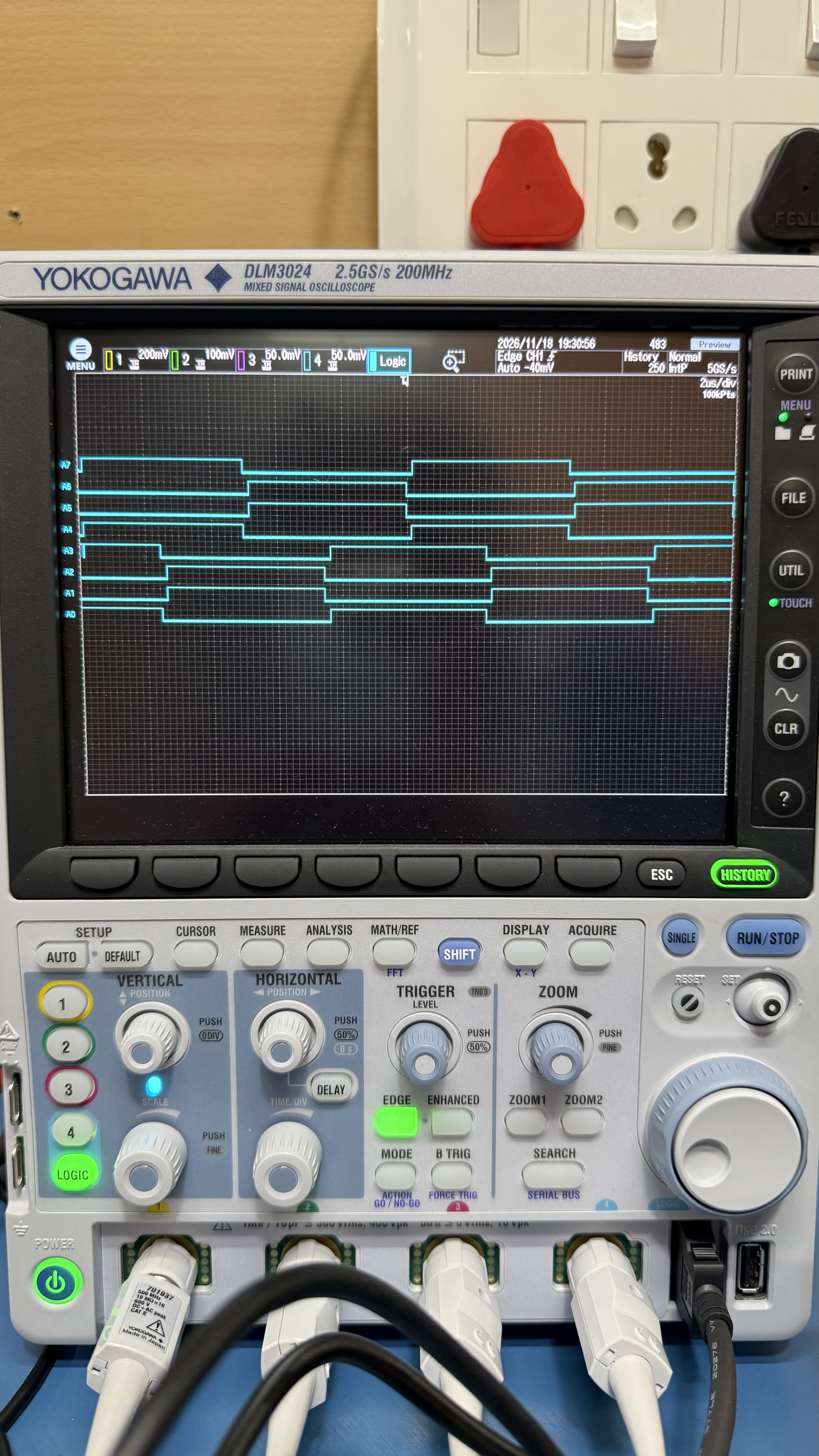
We are pleased to inform you that we were able to successfully test the controller board and generate the PWM pulses.
I have attached a photograph as proof of the successful PWM generation for your reference.
Thank you once again for your valuable support.
~Anusha
 0
-
Hello Anusha,
I'm glad that worked and that you have the system up and running now! I will close this discussion for now but if you have a follow up question, please "Start a New Discussion" and we would be glad to support you further.
Thanks,
Chris N.0