Question about juction temperature
hello, i have a question about junction temperature.
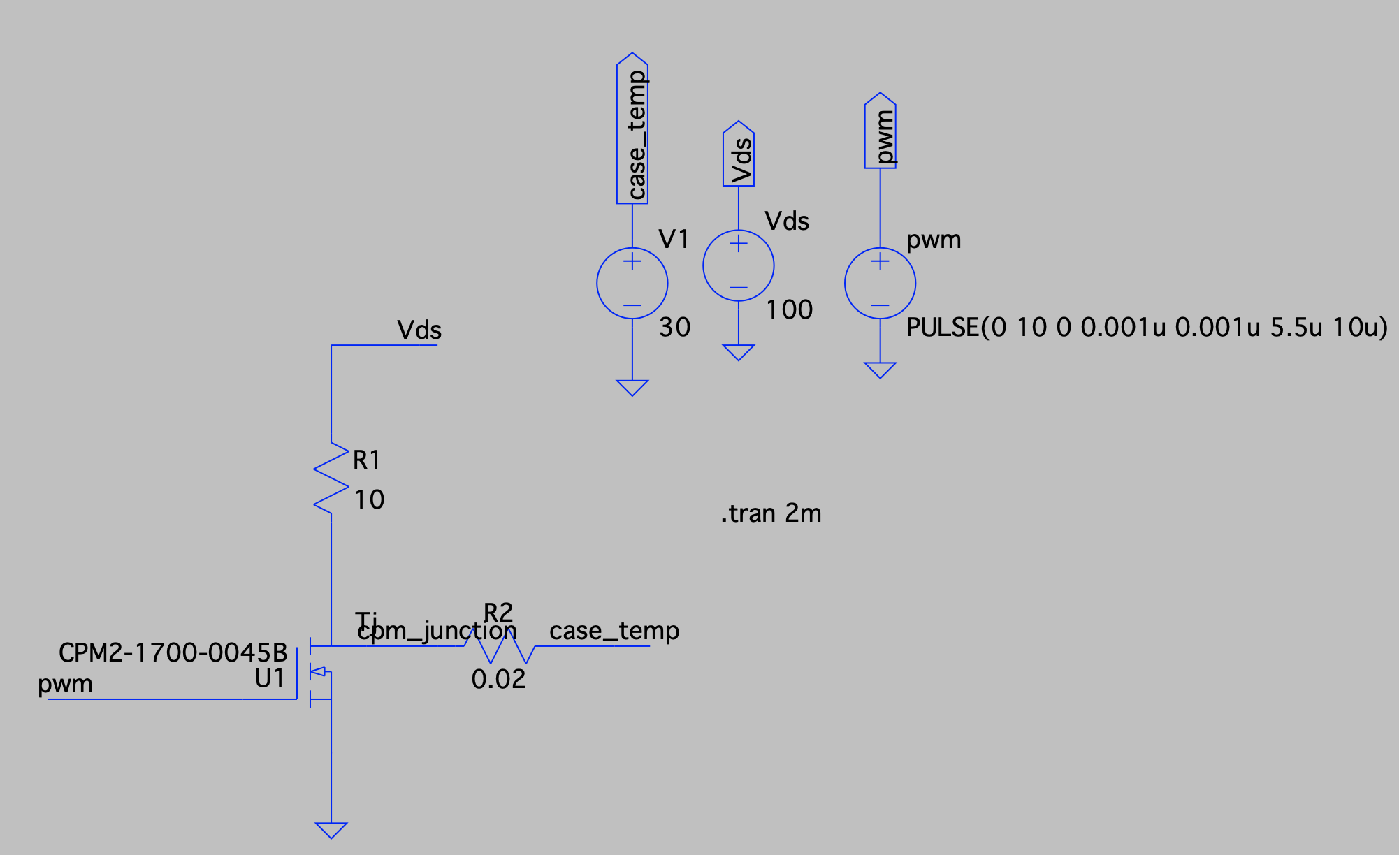
I thermal simulation the chip (CPM2-1700-0045B) in LTspice.
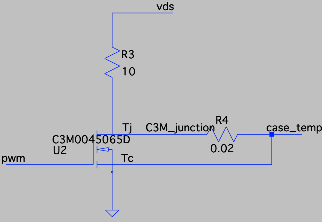
However, I don't understand because it is very different from the chip (C3M0045065D) result.
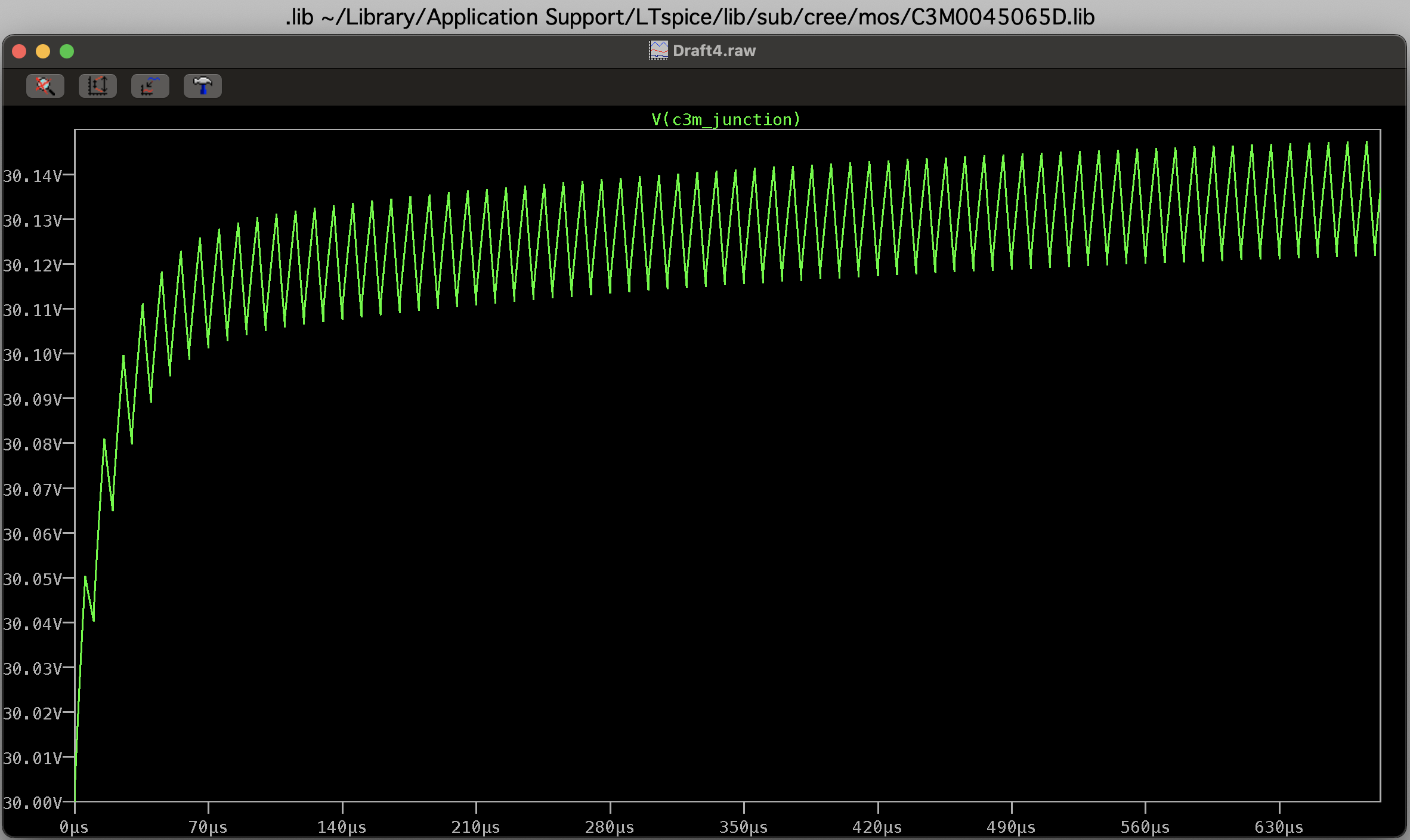
The result of the chip (C3M0045065D) is that the heat gradually increases and then enters a steady-state.
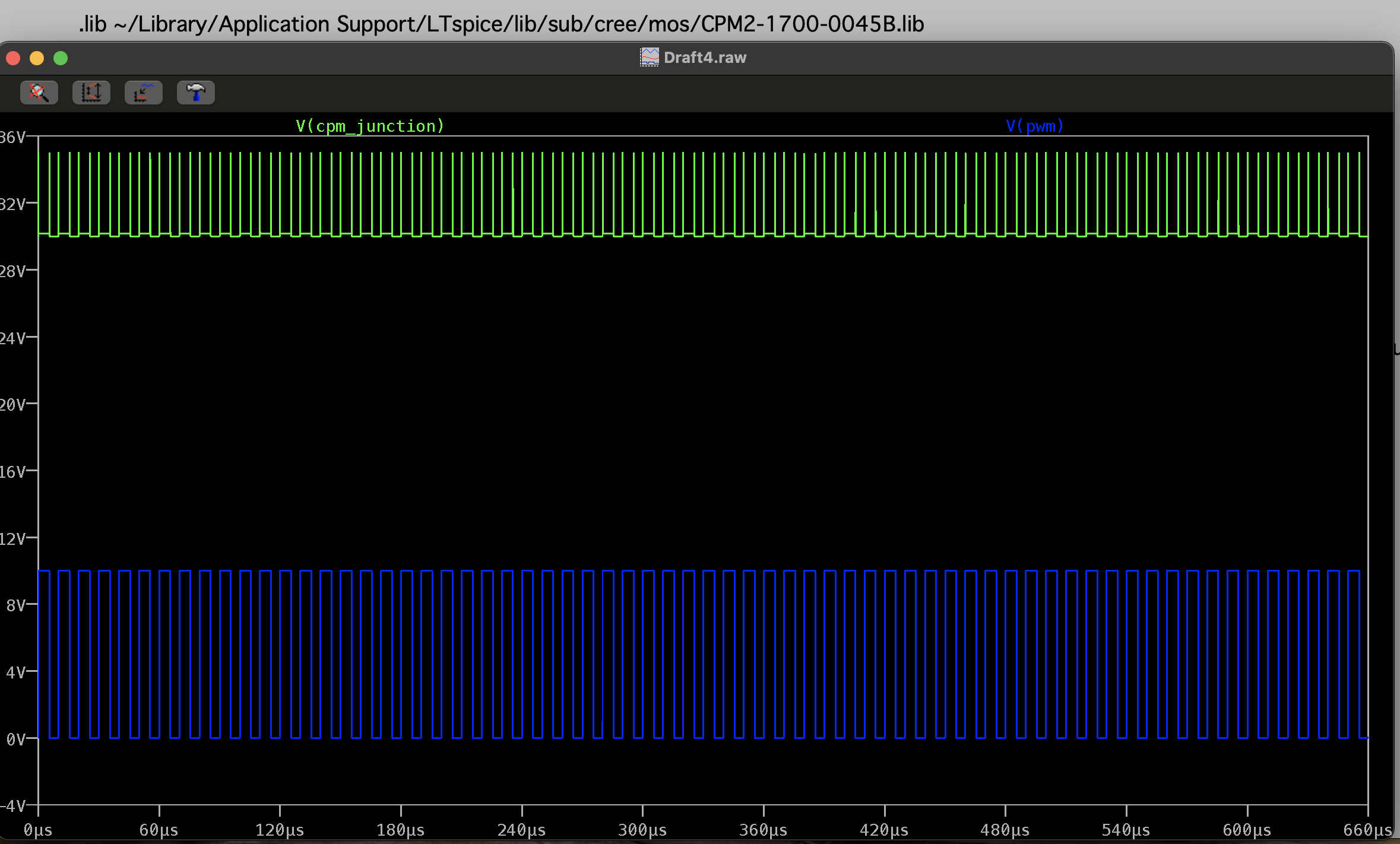
but, in the case of chip (CPM2-1700-0045B) heat is generated only when switching is on/off, and heat disappears again in conduction state.
In my opinion, it is correct to gradually increase and then enter a steady-state like the result of chip (C3M0045065D).
Finally, I have two questions.
First, the chip (CPM2-1700-0045B) result come out properly? if yes, what is the junction temperature of chip?
Second, if the result of chip (CPM2-1700-0045B) is not correct, where should fix it?
Please let me know...😔
Comments
-
Hello,
Great questions. The difference in the two devices you are testing is that C3M0045065D is a packaged device (TO-247), and CPM2-1700-0045B is a bare die that customers can integrate into a custom module.
The die model is behaving as expected in your simulation. A bare die has extremely small thermal mass by itself, and as a result, its temperature will change rapidly based on the instantaneous power dissipation. That is why it has large temperature spikes at the switching edges where the instantaneous power is highest. If you look closely you can also see a small increase in temperature during the on-time compared to the off-time as a result of conduction losses. In order to properly model the die in the end application, it is necessary to add a capacitor in parallel with the Rth_jc resistor to simulate the thermal mass and time constant of the module that the die will be mounted in. This capacitance will act to filter the temperature and result in similar behavior to what you are seeing with the TO-247 model where there is temperature ripple, but also a steady-state average temperature rise.
Also, as a note, the packaged device models such as C3M0045065D have the Rjc built into them, so for these devices, you can attach the "case_temp" signal to just the Tc pin, and use the Tj pin just for measuring. Alternatively, you can attach a voltage source directly to the Tj pin if you want to simulate with a fixed junction temperature.
0 -
@chocolet3018 If your question has been answered, would you kindly click on the link in the post (Example below) so we may close this post ?
0


