SpeedFit™ Design Simulator
Simulate and evaluate the performance of SiC-based power circuits and determine the right SiC device in seconds.
Start a SimulationCRD-06600FF065N-K

Hi, CREE WOLFSPEED,
I am evaluating the reference design of CRD-06600FF065N-K
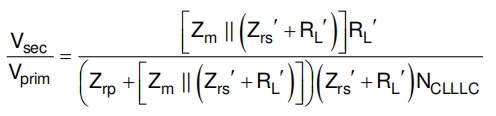
the transfer function of DAB-CLLLC is
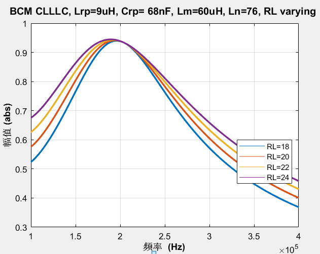
The gain vs frequency plot of CLLLC transfer function illustrates the non-monotonic in the [148kHz, 300kHz] frequency region when I Substitute parameters into the transfer function, as my understanding, which will lead to loss of ZVS on the primary FET, and more critically, the loss of control.
The key parameters of CRD-06600FF065N-K listed below:
Lrp=9uH, Crp=68Nf, Lm=60Uh, turns ration n=15:14
The second resonant parameters is identical to the primary.
my question is why choose this resonant parameters ,and how to make sure the system operation stably.