
SpeedFit™ Design Simulator
Simulate and evaluate the performance of SiC-based power circuits and determine the right SiC device in seconds.
Start a Simulationcurrent and encoder sensors' data

enrico1
Contributor Level 1
Hello Wolfspeed community,
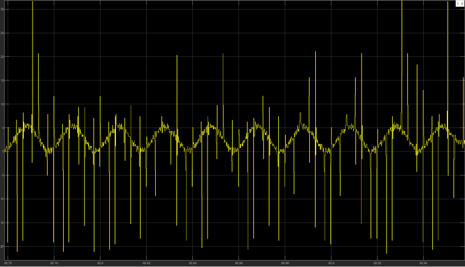
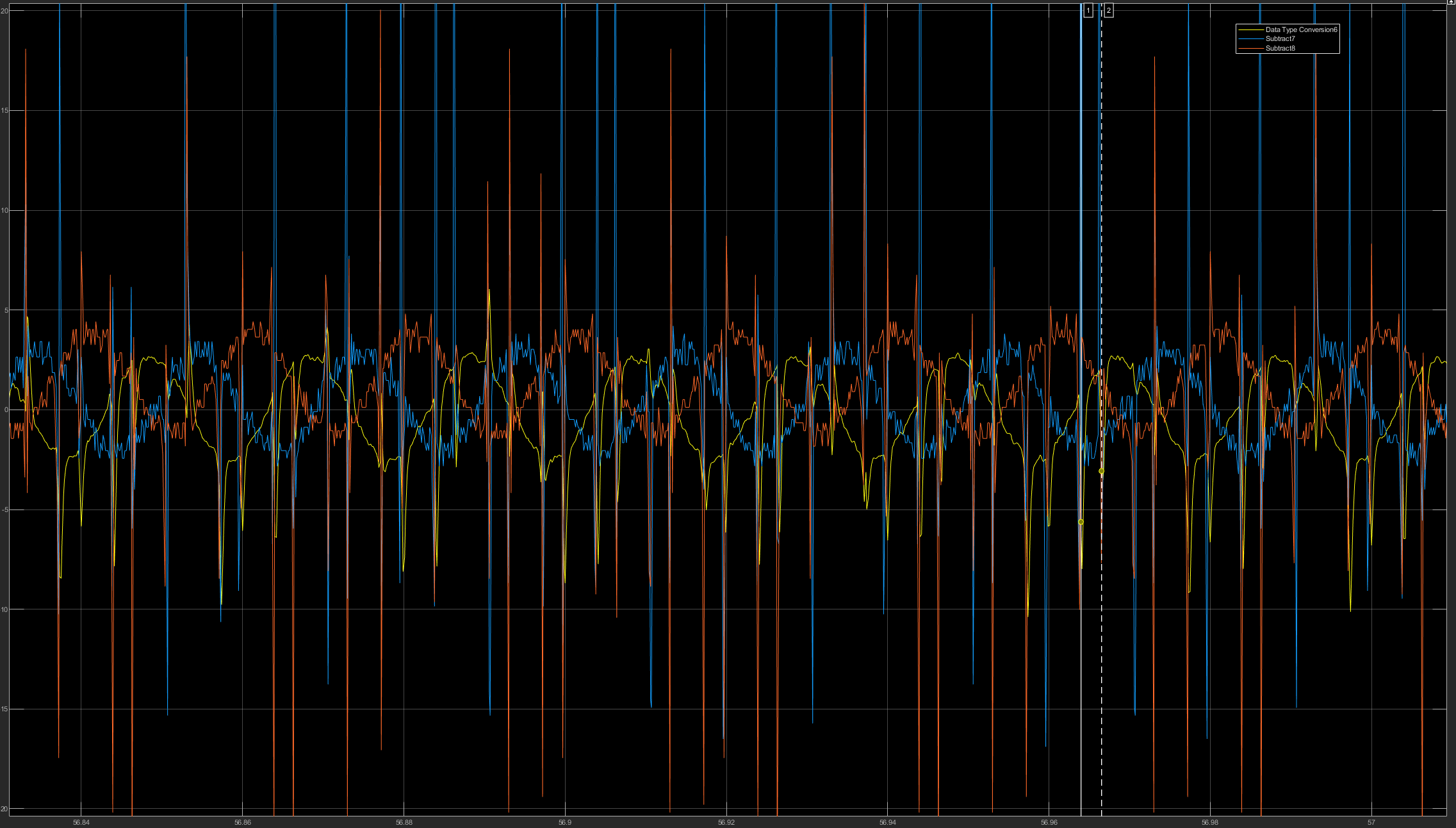
I am trying to create a closed loop control for the inverter CRD300DA12E-XM3 300kW Three-Phase Inverter | Wolfspeed, the current I acquire is very disturbed since the acquisition PIN ADC of the micro 0V - 3V. (same situation also for encoder)
The current I acquired is shown in the following picture with I=2.5A rms and T sample=1*10^-4 s.
With these shapes, the regulator follows an incorrect behavior and the response is wrong.
Have you found a similar problem? How could I fix this?
Thank you in advance
Enrico
0
This discussion has been closed.