
SpeedFit™ Design Simulator
Simulate and evaluate the performance of SiC-based power circuits and determine the right SiC device in seconds.
Start a SimulationCRD-30DD12N-K reference design : the three-phase current measurement strategy

Hello,
With respect to the reference design of CRD-30DD12N-K, I have a few questions on the three-phase current measurement strategy.
Let me describe it with the phase C current as an example.
The current measurement circuit for phase C on the main board is uploaded as below.
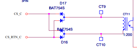
The phase C current is measured by the 1:200 current transformer and it is full-wave rectified by the diode bridge circuit.
The current measurement circuit for phase C on the control board is uploaded as below.
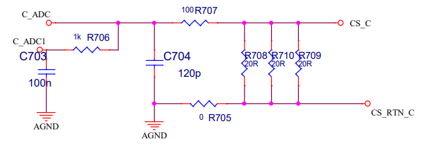
The current signal is converted into the voltage signal by this circuit.
Now I have a few questions on these phase current measurement circuits as follows:
(1) When the current signal is full-wave rectified as aforementioned, how can the DSP know the direction of the alternating current signal?
(2) Why are two signals of C_ADC and C_ADC1 input to the DSP? It seems that C_ADC1 is just a filtered signal of C_ADC.
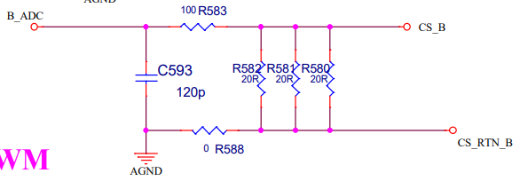
Meanwhile, for phase B, only the B_ADC signal is input to the DSP. There is no B_ADC1 signal as uploaded below.
What is the reason?
Thank you for your consideration.
With regards,
GKIM