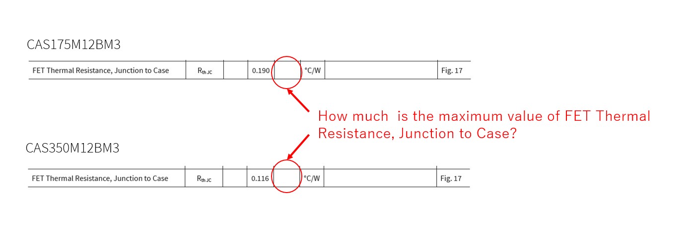
FET Thermal Resistance, Junction to Case of CAS175M12BM3 CAS350M12BM3.
Dear support member,
I have a question about FET Thermal Resistance, Junction to Case of CAS175M12BM3 CAS350M12BM3.
How much is the maximum value of FET Thermal Resistance, Junction to Case?
Best regard.
Comments
-
MaruOkada,
We cannot provide a maximum value for the thermal resistance of these modules.
Best Regards,
Austin C.
0 -
Hi Austin C,
Thank you for your reply.
Why can't you provide a maximum value for thermal resistance?
The BM2 series, for example CAS120M12BM2, shows the maximum value.
Could you teach the reason why you can not provide it?
Best reagrd.
0 -
Hi, Austin C.
How is your progress?
Best regards.
0 -
Hi, Austin C.
How is your progress?
We look forward to hearing back from you.
Best regards.
0 -
Hi MaruOkada,
Older Cree datasheets included this information, but Wolfspeed power module datasheets no longer publish this value. The thermal resistance cannot be directly measured during end-of-line validation due to the length of the test; therefore, a precise maximum limit for RTH cannot be provided. There are other checks in place to guarantee the quality of the thermal stack, but it cannot be translated to an RTH value, so the maximum value for RTH is omitted from the datasheet.
Best Regards,
Austin C.
0 -
Hi, Austin C.
Thank you very much your answer.
I understand that it cannot be provided, but since there is no maximum value when designing, my customer having trouble designing it.
May I ask add question?
Q2
How many times the Max value is the Typ value?
Should I think how many times how many times the Max value is the Typ value?
Best regards.
0 -
Hi, Austin C.
How is your progress?
We look forward to hearing back from you.
Best regards.
0 -
Hi, Austin C.
How is your progress?
We look forward to hearing back from you.
Best regards.
0 -
Hi, Austin C.
Did you have something?
We look forward to hearing back from you.
Best regards.
0 -
Hi MaruOkada,
For the customer's design, you can recommend the same typical-to-max multiplier that the CAS120M12BM2 datasheet illustrates.
Thank you,
Austin C.
0 -
Hi, Austin C.
Thank you very much for your answer.
Best regards.
0 -
Hi Austin,
Can I ask you some questions about thermal resistance of GM3 module.
Since datasheet of GM3 module only provide Rth_jh parameter, what is value of Rth_ch that I can input in the speedfit simulation?
In addition, if default value of Rth_ch 0.1K/W is suitable, 0.1K/W is the total resistance of module, and 0.2K/W for high or low side position, right? thanks a lot
0 -
Hi Tangwei,
The PLECS models of all Wolfpack power modules use the datasheet Rth,jh value in their thermal model, meaning that the Rth,ch is already included in the model (and therefore in SpeedFit). So, the correct Rth,ch is 0 K/W, and SpeedFit has no issues with this value.
The bigger picture however is that the value for Rth,ext should not be zero (as Rth,ha is non-zero). It generally won't result in significantly different simulation results if you use a fixed Th and set Rth,ch = Rth,ext, or if you use a variable Th and set Rth,ch = 0 & Rth,ha = Rth,ext. If you have an estimate for the thermal mass of the heatsink, using the variable method is slightly more accurate.
As for values of Rth,ext, it changes with package design and scales with die area. I would recommend these values:
These values were measured as part of the Zth characterization process and represent typical performance for a low cost liquid cooling solution. Consider them a rough starting point for your simulations as much lower values can be achieved with more expensive cooling solutions, while forced air cooling would be slightly worse (i.e. higher Rth,ext values). Passive air cooling would be significantly worse than the values shown here. We would of course recommend hardware validation to confirm your thermal management system is suitable for the application.
Hopefully that addresses your question. Thanks,
Blake
0 -
Hi Nelson,
Thanks for your detailed reply, so what is the parameter- Rth_HF you mentioned (heatsink to ?), can you please provide some learning articles in WS for better understanding, thanks
0 -
Hi Tangwei,
The modules application team is developing a detailed app-note on thermal analysis and parameters for our power modules. It will be releasing in the coming weeks, and will be in our document library https://www.wolfspeed.com/document-library/?productLine=power. I'll try to post a link to this thread as well.
Rth,HF is describing heatsink to fluid, as the data was measured with liquid cooling. Again, you will need a higher value if your are simulating air cooling. Rth,HA would be heatsink to ambient, and is how I would describe air cooling.
Thanks,
Blake
0 -
0
-
Hi BlakeNelson,
thanks for your kindly support, can you tell the name of application note you will release in the document library ? thanks a lot
0 -
Hi Tangwei,
Right now the working title is "Power Module Thermal Validation Application note," and we expect it to release at the end of August.
Thanks,
Blake
0 -
Great, thanks
0


