CGD1700HB3P-HM3 Overcurrent Detection
Hello Wolfspeed-Team,
I am working with your CAB760M12HM3 half-bridge module and the CGD1700HB3P-HM3 driver board. I want to use the modules LS-transistor in a short-circuit testbench as the high-side switch and for protection. When the DUT faults the current is rising to a very high value (over 8kA) which I hope would trigger the over-current-detection of the driver board. At the moment I connect the Pins as follows:
1 +12V | 2 GND | 5 +5V | 6 -5V| 15 +5V
I can drive the switch as intended but the Over-Current Protection does not latch, although it looks like it is triggered. What can I do different to use the over-current-protection as intended and only reset it after the user decides to?
Greetings
Sönke
Comments
-
Sönke,
Thanks for reaching out. The connections you have described sound correct with the exception of the low side PWM, which should be +/-2.5V. However, that does not explain the issue you are describing. Could you share scope captures of the DESAT appearing to trip but not latch?
Just to be clear during DESAT event a soft shutdown is initiated so the output gate signal will decay slower than the standard turn off event. I am not able to replicate the behavior you are observing on the bench.
0 -
Hey Paul,
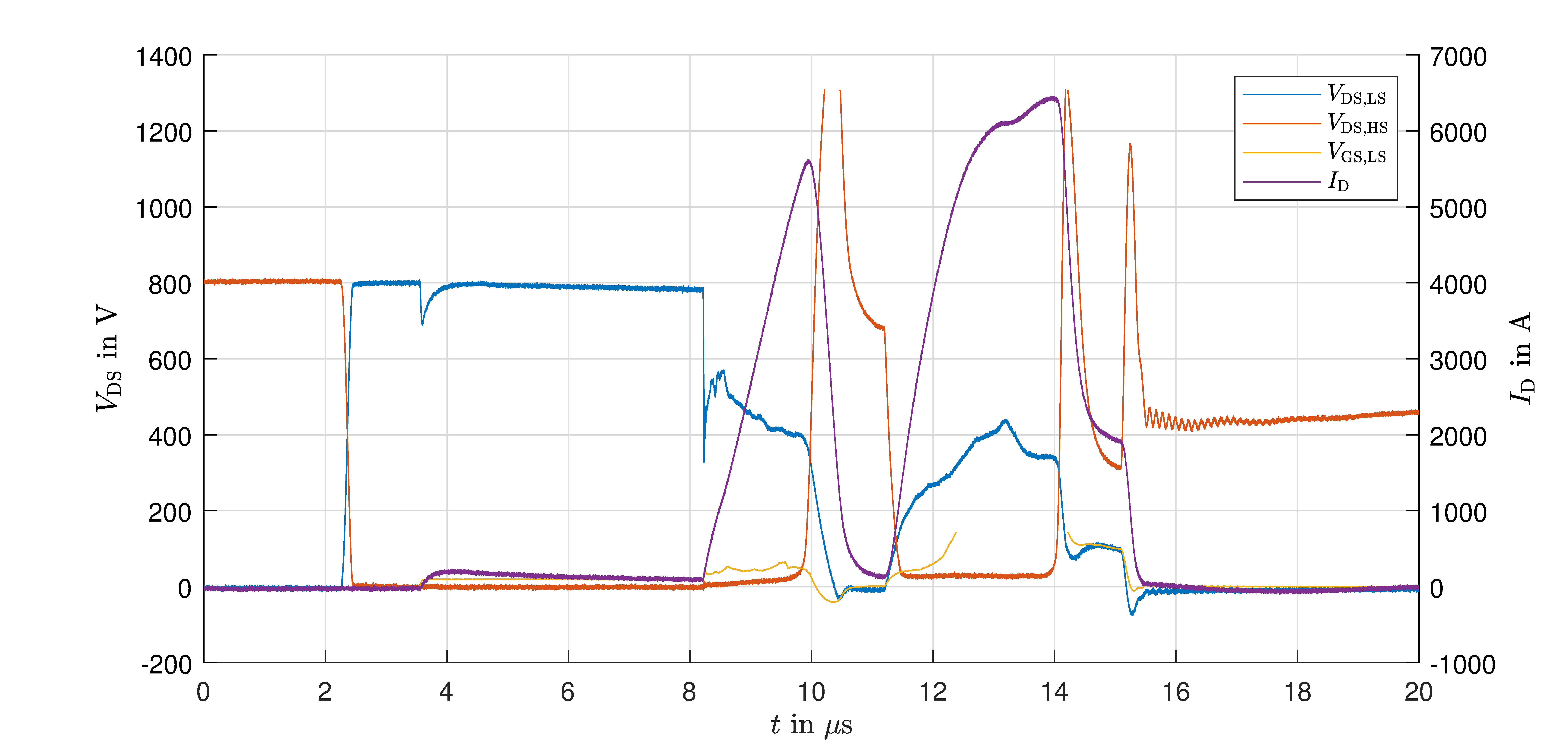
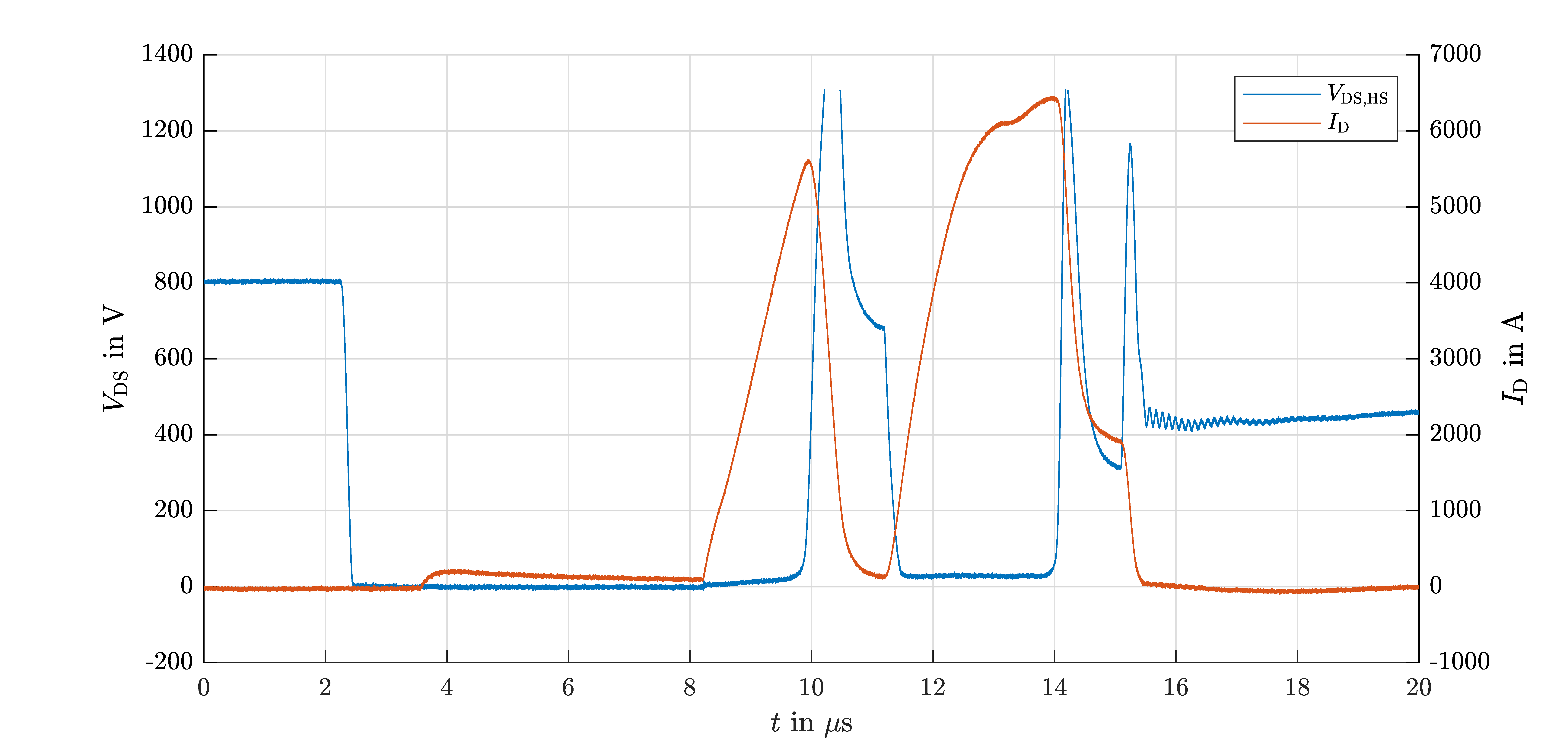
thank you for your response. In the attached plots I have the Signals I measured when the over-current-protection should react. V_DS,HS is the voltage measured for the lowside of CAB760M12HM3. While V_DS,LS and V_GS,LS is the DUT that is destroyed.
You are correct, I have the wrong PWM with +/- 5V but as you said, I don't think that is the problem. Is it necessary to connect any of the other Pins for example PIN 7 or PIN 8?
Greetings
Sönke
0 -
Hey Sönke,
Thanks for the attaching the waveforms. Pin 7 and 8 are just to report the fault to your controller through our differential transceiver board. It is not necessary to connect those pins for proper functionality.
The latching of the DESAT signal for the low side is controlled by the D-Flip Flop, UT15. The initial successful soft shutdown from your waveforms indicate that the gate driver board is not damaged. The reset must be being triggered by external noise on the reset line. Have you observed this behavior when using only the onboard pull up RB56 and nothing connected to pin 15? How is your reset signal routed to the gate driver and pulled up to 5V? I am still unable to replicate the false reset trigger.
Thanks,
Paul Kanatzar
0 -
Hello Paul, sorry for the late response and thank you for your comments. We made some measurements with our control PCB and noticed major noise at the switching events. We came to the conclusion that this will trigger a false reset. So you are correct and we have to redesign our control unit. Can you give any advice on how you implemented the control signals and the supply of the DC voltages as well as the reset control?
Greetings Sönke
0 -
Hey Sönke,
The general guidance is to keep the signals as far away from the high current loads and as short as possible. Near the connection to the gate driver you may add a ferrite ring around the signal wires to reduce common mode noise.
If that is not practical in your system you may be able to increase the size of the filter capacitor on the driver board itself.
0 -
Hi, I hope that this answered your question. I will close this discussion for now but if you have a follow up question, please "Start a New Discussion" and we would be glad to support you further.
0


