Problems with the commissioning of KIT-CRD-3DD12P
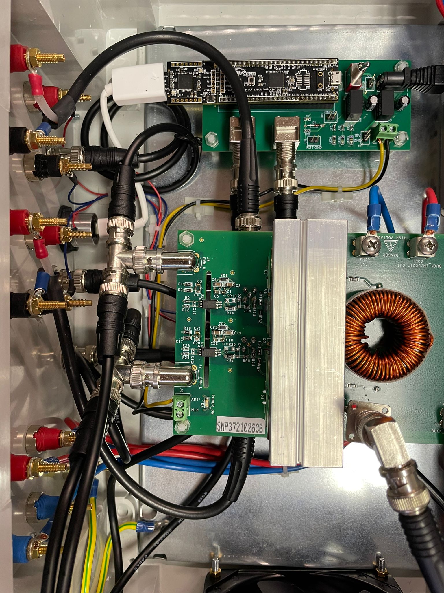
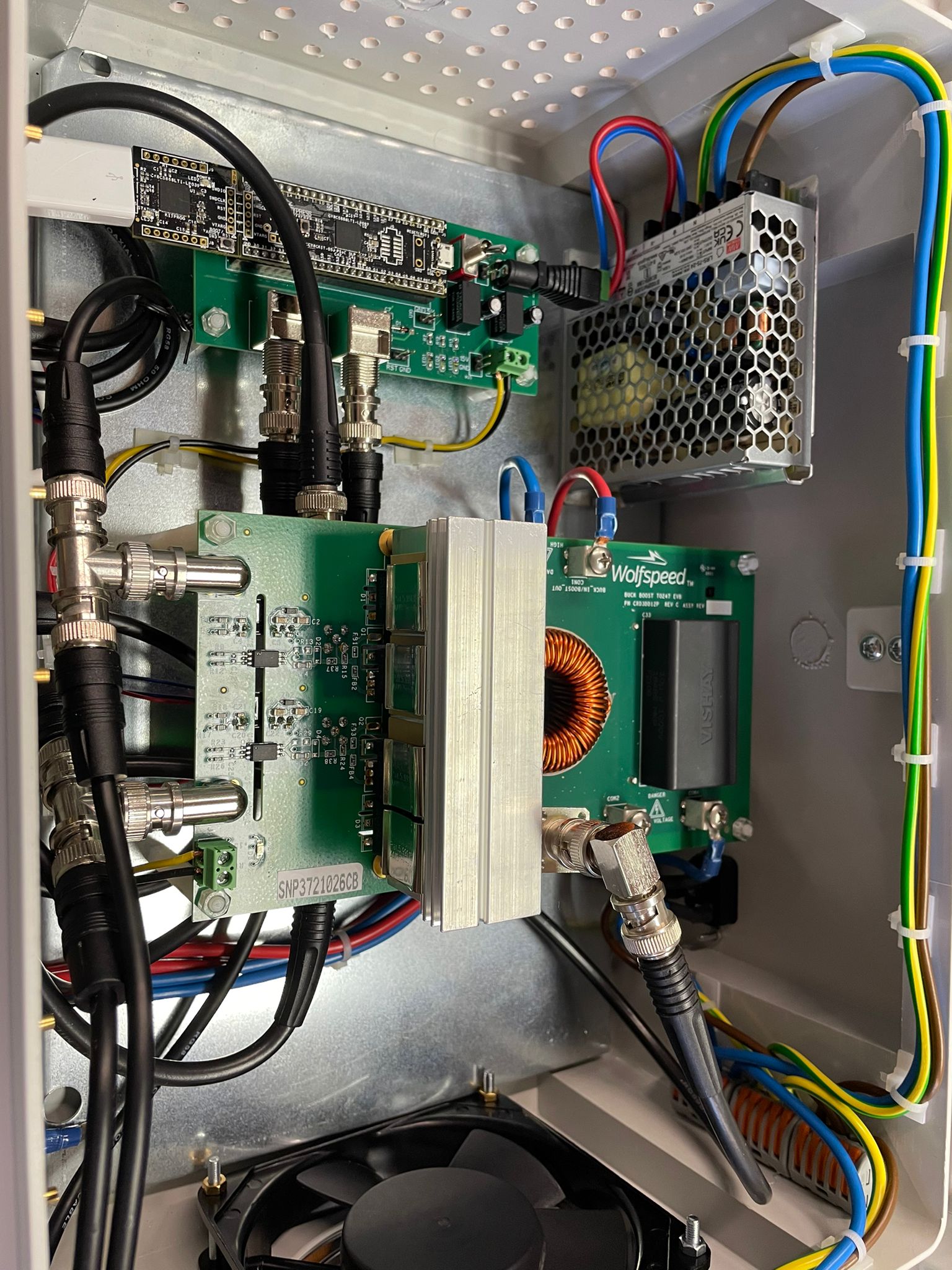
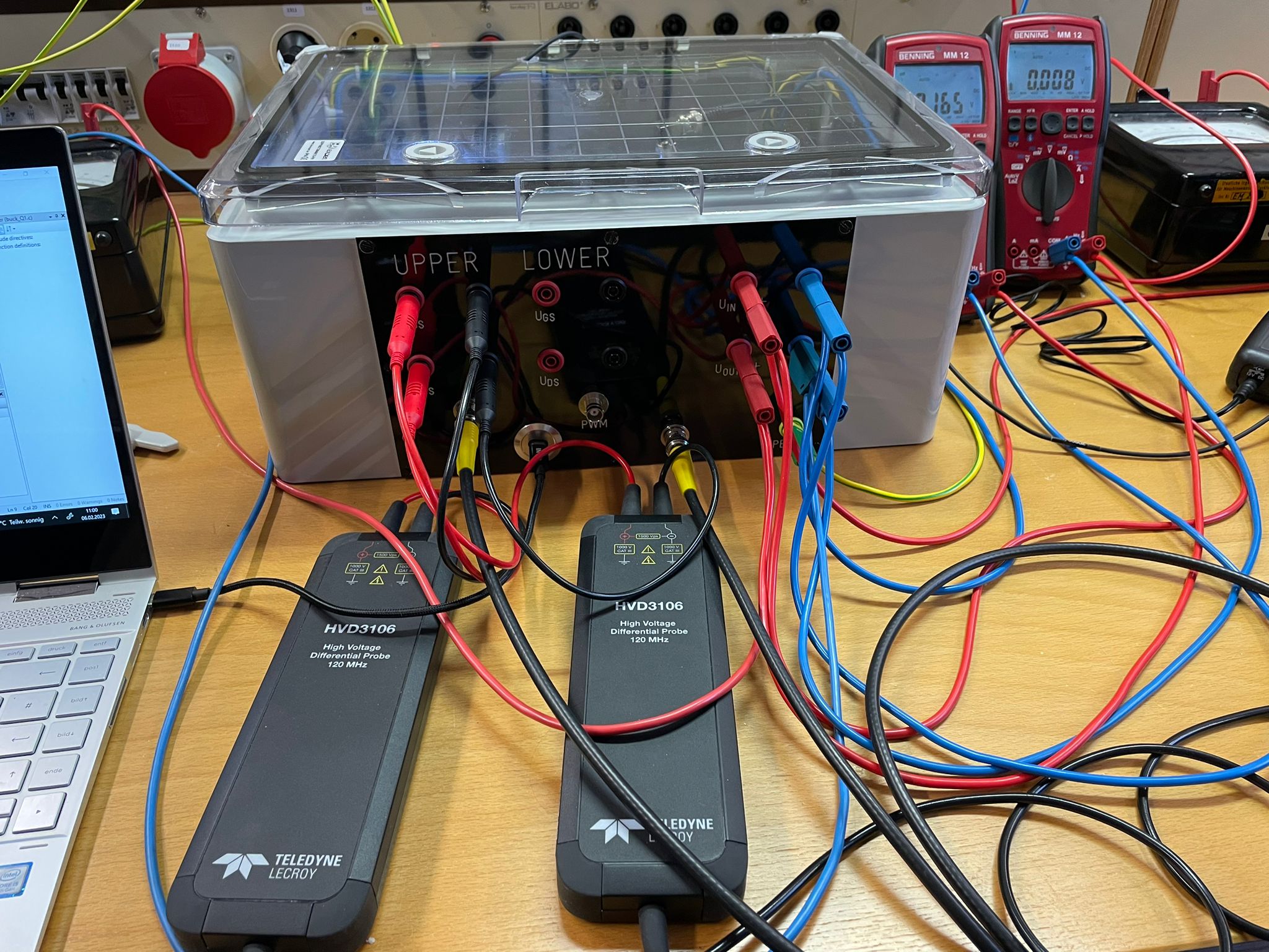
In a test configuration, I want to compare the switching behavior of an asynchronous and a synchronous buck converter. The mosfets are controlled by PWM.
The evaluation kit contains two mosfets and two diodes (C4D10120D). The current measuring resistor is also attached.
During the measurement, it can be seen that a high current is flowing. The output voltage does not correspond to the expected output voltage. It is far too small. What could be the problem?
Comments
-
Hello sladanavucic,
Can you please provide more details about the system and also attach some Vgs, Vds and current waveforms?
When is the output voltage lesser than what you're expecting- during the asynchronous test or synchronous test? Are you operating it as a Buck or Boost?
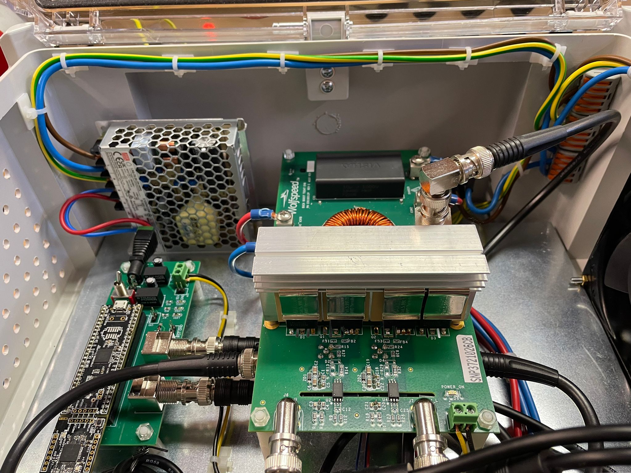
Can you also attach an image of your test set-up?
Thank you!
0 -
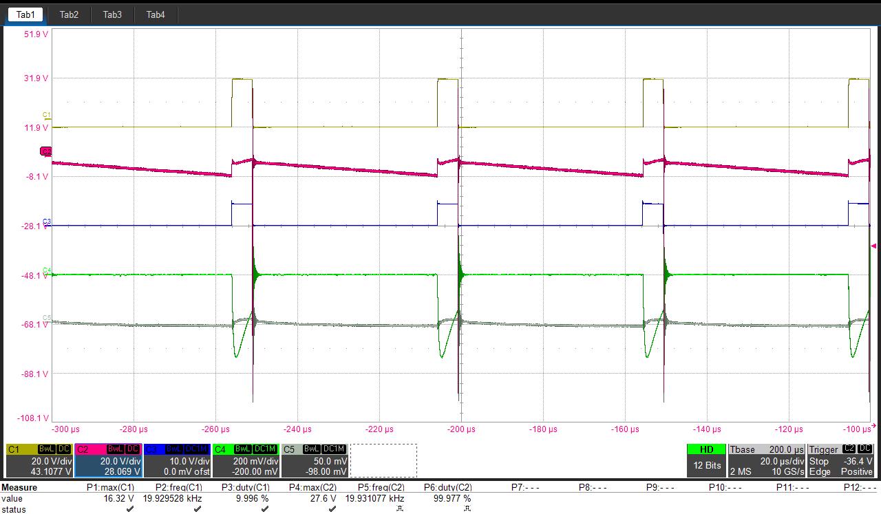
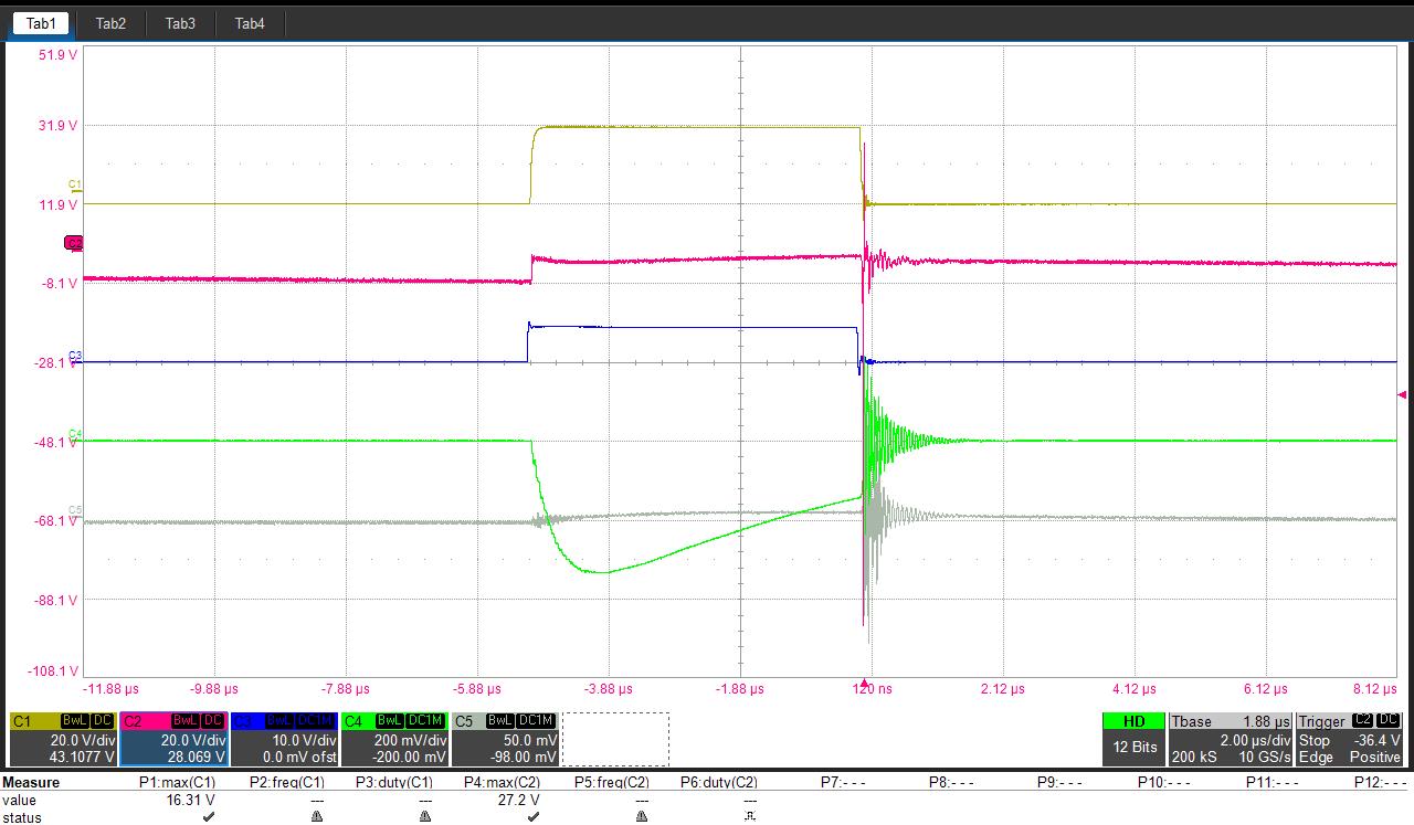
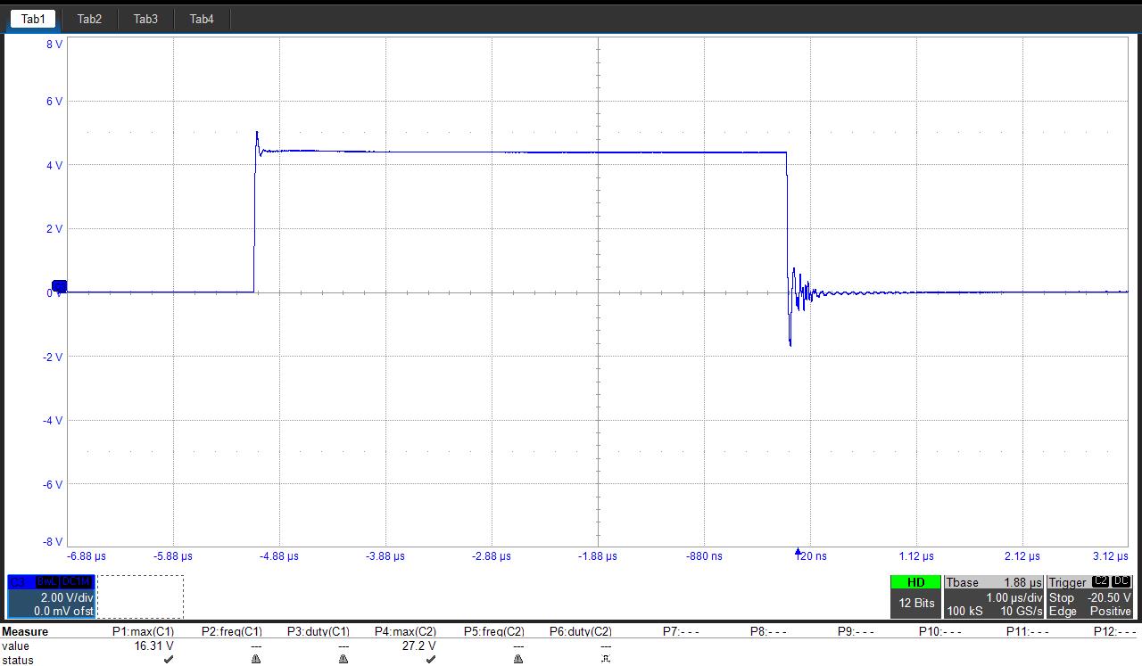
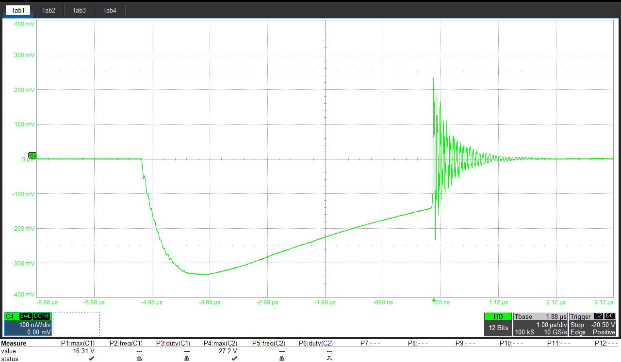
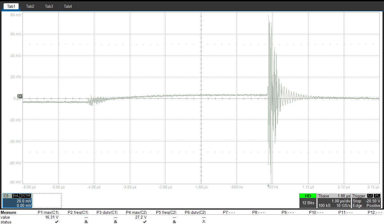
The evaluation kit is operating as buck converter. During the asynchronous test the output voltage is lesser then expected. At input voltage of 5 V the input current was around 2,5 A. The duty cycle was 10%.
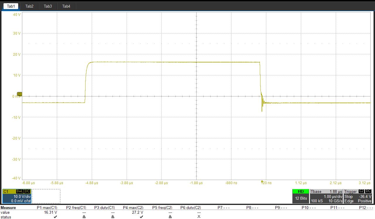
C1: Gate-Source Voltage
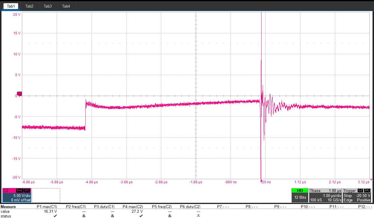
C2: Drain-Source Voltage
C3: PWM
C4: Drain Current
C5: Current ripple
0 -
Hello sladanavucic,
We've reached out to you over email to better understand the detailed system you're working with so we can better help you. Thank you!
0 -
Hello sladanavucic,
I hope our discussion over call has answered your questions. I will close this discussion for now but if you have a follow up question, please "Start a New Discussion" and we would be glad to support you further.
0

