Gate source voltage measurement of SiC module
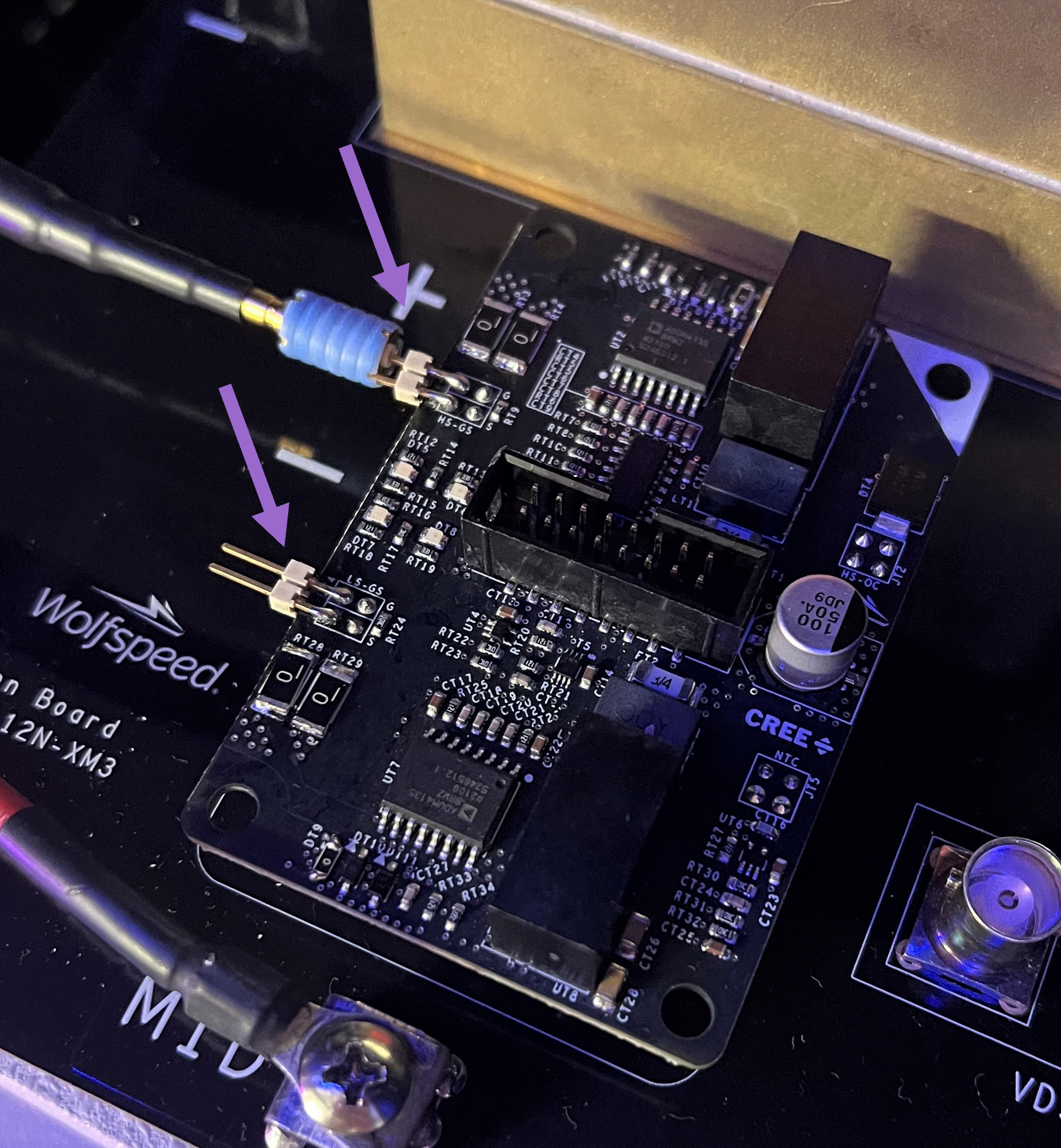
Hello, I bought your half-bridge module CAB450M12XM3 and used CGD12HBXMP to drive it, but there is no measurement pin reserved for the gate source voltage(vgs) on the driver. How can I test the gate source voltage(vgs)? Is it necessary to connect two wires directly from the two welding points G and S on the drive board for measurement?
Comments
-
Hi baiyujing,
You are correct; there is no direct measurement connection point on the CGD12HBXMP. In our lab, we typically solder on a 2-pin, 0.100" header as shown below to connect Tektronix IsoVu probes. You could also solder on wires as you described.
As a word of caution, if the gate driver does not work after performing the soldering, there may be a gate-to-source short between the G-pin & the copper surrounding the pin as the spacing is tight. It's possible to burn or scrape through the soldermask that conceals the Source plane if the iron is left on the surface for too long creating a short. If this occurs, clean up the soldering on the G-pin and the gate driver should work without issue.
Best Regards,
Austin C.
0 -
Thank you very much. This answers my question. Also, what kind of probe is used to test vgs in your laboratory? Can you tell me its model? So I can buy the same one.
0 -
In addition, according to my understanding, there are two pins for G and S respectively. Is it because the opening and closing signals need to be input separately? If so, should all four pins be led out?
0 -
Hello baiyujing,
We use the Tektronix® IsoVu Isolated Probes for VGS measurements. More information on the probes can be found here: https://www.tek.com/en/products/oscilloscopes/probes/isovu-isolated-probes
The two pins are for redundant Gate & Source connections between the driver and the module, which provide lower gate loop inductance & higher reliability compared to a single pin design. For further clarification, the Gate pins and Source pins are connected internally in the gate driver PCB, so measuring a single pin as shown in the picture above will achieve the same measurement as connecting both sets of pins.
Best Regards,
Austin C.
0 -
Thank you for your answer. I also want to inquire about the application of CAB450M12XM3. I know that a CVR is generally designed on the evaluation board as a measurement interface for the current flowing into the module, but in practical application, it is usually to directly measure the current flowing through the wire with a current clamp? So, because the current flowing through CAB450M12XM3 is very large, do we need to design copper bars to replace ordinary wires? If yes, how is the current flowing through the copper bar measured? If not, can you tell me how your laboratory works? It would be better if you could give me a system measurement scheme for voltage and current when applying CAB450M12XM3
0


