Reference design of CRD-22AD12N: datasheet for the AFE heat sink
Hello,
With respect to the reference design of CRD-22AD12N, the AFE heat sink is employed in the main board.
In the excel file of Main_board_BOM, its description is listed as 22kW AFE heat sink 190*400 mm.
However the exact part name is not available.
Would you please share the datasheet for the AFE heat sink ?
Thank you for your consideration.
With regards,
GKIM
Comments
-
Hello, thank you for your message. A member of our technical team is looking into your questions and we will respond shortly.
0 -
Hello,
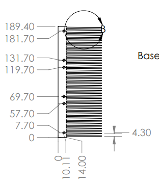
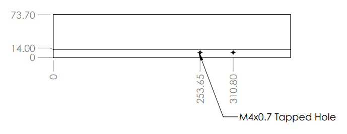
Please see the attached drawings for the heatsink as well as the bracket that holds the fan for the inductors. These are custom parts and do not have a manufacturer's part number.
Thanks,
Adam
0 -
Hi Adam,
Thank you for sharing the drawings.
Reviewing two drawings for the heatsink and side fan bracket, I have two questions as follows:
(1) It seems that three cooling fans are installed at the heatsink side which is 190mm long.
It looks that six holes shown in the captured image uploaded above are to fix three fan brackets.
They may be tapped holes. What are the tap size: M3 or M4?
(2) A captured image uploaded below is associated with the heatsink side which is 400mm long.
There are two tapped holes of M4x0.7. What is the purpose of these two tapped holes?
Thank you for your review.
With regards,
GKIM
0 -
Hello GKIM,
The 3 fans on the 190mm edge of the heatsink get mounted directly to the heatsink with no bracket. Two long screws go through each fan and fan guard into the heatsink holes (M4 size). The bottom two fan holes use a shorter screw and a nut just to secure the fan guard in place, and do not go into the heatsink.
The two holes along the longer edge of the heatsink are for the fan bracket. This fan is aimed at the main inductors.
The model below shows the configuration.
0 -
Hi Adam,
Thank you for your review.
I now understand the overall configuration for the heatsink and cooling fans.
Meanwhile would you please share the part number for the cooling fan?
It is not listed in the BOM.
Thank you for your consideration
With regards,
GKIM
0 -
Hi GKIM,
Please see the attached top-level BOM which includes the fans.
Thanks,
Adam
0 -
Hi Adam,
Thank you for your assistance.
Please let me close this discussion.
GKIM
0


