Overcurrent Protection Trigger - CGD12HBXMP
Hello all,
I am testing a 3 phase inverter/drive for which I have designed the control board myself.
Below I am listing the parameters of my system:
- VDC = 750V
- DC-Link Cap = 330uF; 1100V Rated
- Fswitching = 15 kHz
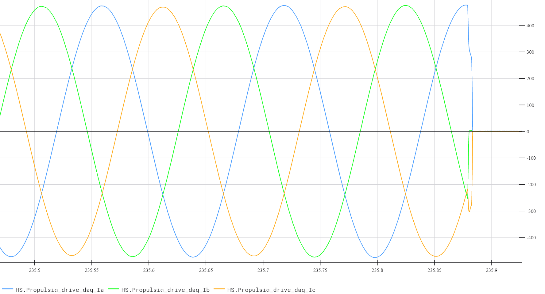
On this drive there are three Wolfspeed modules installed (CAB450M12XM3) with their respective gate drivers (CGD12HBXMP). After connecting the drive to a 3 phase motor and trying to ramp up the current output by using current control method, I see that an Over-current protection fault is triggered (LEDs DT6 and DT8). This happens always at a phase current amplitude just above 400A.
To make things more interesting it seems that the fault does not always occur on a specific phase/gate driver or a specific side (high-side/low-side switch). It seems to be a little random. Moreover, the temp
rature of the power modules suggests that nothing should be wring. At least nothing related to high currents in the system.
Reading the gate-driver datasheet I see that the over-current trip point is at 1000A and this is far from what I am pushing through the power modules.
I have tried the following:
1) Swapping gate-drivers assuming that some of them might be faulty
2) Measuring current sensor output while operating to confirm that the readings of the current sensors are correct
3) Making the cables to the motor as short as possible so that I introduce as little inductance as I can
4) Increasing the Rgate on the gate-drivers assuming that this issue is caused by a voltage overshoot while switching (dead-time was also adjusted accordingly)
I have been trying to find a solution to this issue but so far nothing has worked. I am also attaching a screenshot of the phase currents measured at the moment that this over-current is triggered.
If anyone has any ideas, suggestions and recommendations, I would really appreciate it.
Best regards,
Konstandin Kotsis
Comments
-
Thank you for your post, it has been approved and we will respond as soon as possible.
0 -
Hi Konstandin Kotsis,
Thank you for including the thorough information with your query. The behavior you're describing is typical for a stock CGD12HBXMP gate driver. The trip current of 1000 A in the driver datasheet is provided for a test condition with the junction temperature at 25°C, but at an elevated junction temperature the trip current will decrease. Please refer to Figure 1 in the CAB450M12XM3 datasheet to find a suitable trip voltage across all operating parameters including junction temperature and peak current (including ripple).
To increase the trip current, replace the Zener diodes DT3 and DT9 with a lower Zener voltage part. The Zener diode should be in a SOD123 package such as the diodes in the PDZ-GW series from Nexperia USA Inc. To continue testing quickly, you can also replace DT3 & DT9 with a 1206 jumper resistor (0 Ω) to increase the trip threshold to approximately 8 V.
Best Regards,
Austin C.
0 -
Hi, I hope that this answered your question. I will close this discussion for now but if you have a follow up question, please "Start a New Discussion" and we would be glad to support you further.
0


