
SpeedFit™ Design Simulator
Simulate and evaluate the performance of SiC-based power circuits and determine the right SiC device in seconds.
Start a Simulationgate-source voltage oscillation when paralleling two C2M0025120D

Hello ,
Now we test a three phase inverter using C2M0025120D, fs=10kHz, each place has two SiC MOS in parallel, totally 12 SiC MOSFETs, performing Double pulse test.
However, when DC voltage and current increase, both SiC MOSFET gate-source voltage start to oscillate at the miller pleteau, sometimes the oscillation even cause failure as shown below.
yellow line: upper leg Vgs green line: lower leg Vgs blue line: upper Vds red line: upper Ids
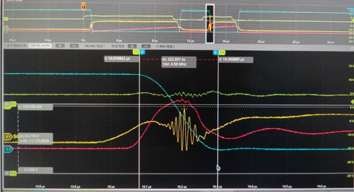
At DC voltage=400V / Ids=20A ,we replace all C2M0025120D with C3M0015065D, under same PCB and test condition, the gate-source oscillation disappear. I'm wondering what difference leads to this phenomenon?
Our parallel MOSFET both use individual turn-on/turn-off resistance, which is 4.7ohm.
We place a 1000pF and 10kohm between each MOS gate-source. From each parallel MOS source to driver IC, we connect an 1ohm in series. Each MOSFET drian-source Cds we put a 2000pF cap in parallel.
My question is: 1. Can you give some suggestion about how to reduce the gate-source turn-on oscillation when parallel SIC MOSFETs?(except for change PCB layout)
2 What difference between C2M0025120D and C3M0015065D leads to different gate-source oscillation phenomenon under the same condition?
Thank you, looking forward to your response.