How to connect the Gate Driver Board (CGD1200HB2P-BM2) with the Power Module CAS120M12BM2
I am trying to generate PWM signal and gate pulses the CGD1200HB2P-BM2 gate drive board with the half bridge module (CAS120M12BM2) . I am supplying 0-5V input signals and 12V power to the board, however the output is not showing any pulses and getting stuck at high or low rail (-5V or + 20V).
No fault lights are tripping. The overcurrent protection pin is connected to the positive side of the half bridge (CAS120M12BM2). There is no voltage applied to the lf bridge during this test (Vds = 0). Reset is pulled low. PWM-EN are pulled high (5V).
How can I generate gate pulse? Please let me know.
Thank you.
Comments
-
Thank you for your post, it has been approved and we will respond as soon as possible.
0 -
Hi Zakir_Hasan,
I believe the issue is due to the PWM input on the gate driver expecting a differential 5 V signal rather than a singled-ended, 0 V - 5 V signal. A differential signal will provide +5 V between HS-P & HS-N during the on-state and -5 V between HS-P & HS-N during the off-state. The easiest way to achieve the correct signaling is by using Wolfspeed's companion differential transceiver board (CGD12HB00D), which can be purchased through various distributors. Here is a link to the product on Digi-Key:
https://www.digikey.com/en/products/detail/wolfspeed-inc/CGD12HB00D/10248982
Best Regards,
Austin C.
0 -
Thank you for your solution. I want to know about the connection of microcontroller to differential transceiver. I have attached the image of of block diagram. I have connected HS-PWM and LS-PWM pin. But for the FAULT, RTD pin, what will be microcontroller pin number?
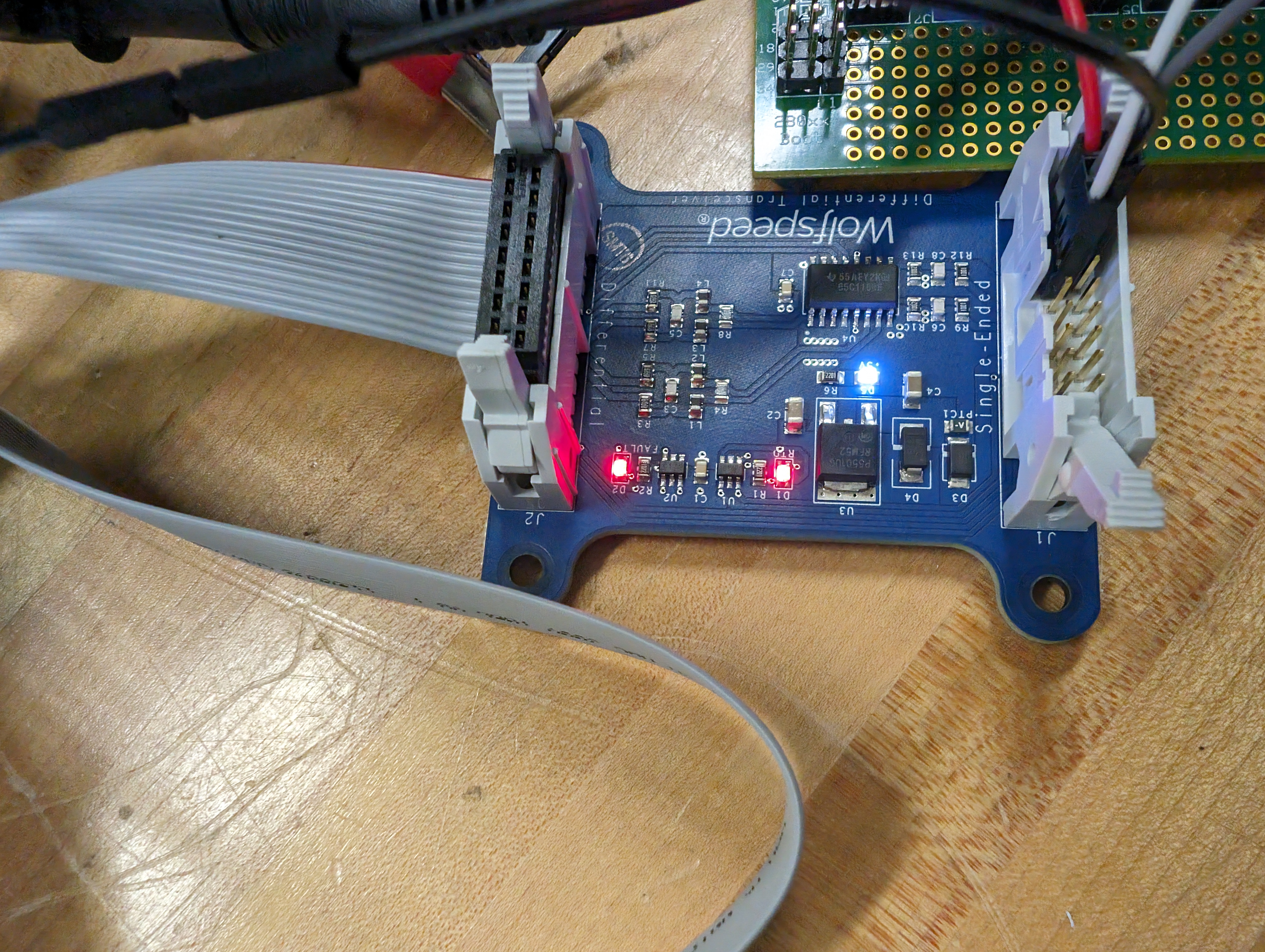
When I have given supply without RTD and FAULT connection, it shows fault in the differential transceiver board. How can I solve this? I have attached the image for your convenience.
0 -
Hi Zakir_Hasan,
Please take a look at the forum thread below. I believe this is your issue with the constant fault status. You'll also want to utilize the RESET pin to clear the fault after applying the recommendations below.
Best Regards,
Austin C.
0 -
Thank you for your help.
Differential transceiver (CGD12HB00D) fault has been solved. I have connected the module into the gate driver. I have found the PWM in the gate driver/module high side switch but have not found any PWM signal in the low side switch/ low side of the gate driver. The gate driver's low side has not turned on. I found only -5 V across it. But in the high side, I found 20/-5 V Vgs voltage.
I have attached a block diagram where I have connected +12 V, ground pin, HS-PWM-P,HS-PWM-N, LS-PWM-P,LS-PWM-N pin from differential transceiver to gate driver. I have not connected any other pins. Is it okay? How can I get the PWM in the low side of the gate driver?
0 -
Hi Zakir,
I have the exact same problem.
Did you manage to resolve your issue?
Kind regards,
Roland
0 -
Hi Zakir and Roland,
Are the fault indicator LEDs illuminated?
Best Regards,
Austin C.
0 -
Hi AustinC,
The D1 (RTD/RTY) fault has not been illuminated yet.
I have connected the MOSFET Module to the gate driver. When I ran the test, it showed no error in the Differential transceiver (CGD12HB00D) at first. But after increasing power (voltage above 6V and current 7~8A) into the module, the D1 LED shows a red indicator.
What could be the reasons for this error? I have not found anything related to this error in the CGD12HB00D datasheet. Could you please clarify?
0 -
Hi Zakir,
The D1 indicator on the differential transceiver is floating/unused when paired with the CGD1200HB2P-BM2 driver board. There is no error if this light illuminates red.
Best Regards,
Austin C.
0 -
Hi Roland,
I have resolved the problem. The problem was in my code. I had not given any PWM dead band signal in low side of the switch and that's why it did not enable the low side. After correcting of my code, It works.
Thank you.
Best regards,
Zakir
0 -
Hi Austin,
Thanks for the valuable information.
Best regards,
Zakir
0 -
Hi, I hope that this answered your question. I will close this discussion for now but if you have a follow up question, please "Start a New Discussion" and we would be glad to support you further.
0


