Hole drill diameter and tolerances for press fit of GM3 module
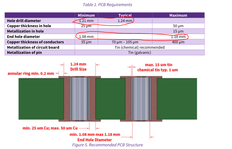
I'm attempting to design a PCB with CAB006M12GM3 module. This is a press-fit module and I've gone through the application note CPWR-AN41. Table no.1 in page 3 specifies that the drill hole diameter should be 1.21 to 1.24mm. However, talking to the PCB fabricator, it looks like they use the metric drill bit where drills are available in increments of 0.05mm. So the fabricator can use either 1.2mm drill or 1.25mm drill. What is the rationale for specifying 1.21mm to 1.24mm? This does not seem be achievable by fractional inch drill bit system either.
Also, the finished hole size should be in the range of 1.08mm-1.18mm, which requires a tolerance of +/-0.05mm. However searching through various PCB fabs online, it looks the minimum tolerance for a PTH hole is +/-0.075mm. Is the tolerance mentioned by the application note achievable in manufacturing?
Comments
-
Thank you for your post, it has been approved and we will respond as soon as possible.
0 -
Hello Anand,
Unfortunately you are referring to an older version of the app note. We have revised it. Please refer to the new version here.
You can also take a look at this reference design - it is inline with our recommendations and uses a finished hole size of 1.10 mm +-0.05. This can be achieved by using a drill size of 45.3 mil (1.15 mm).
0.05 mm (0.002") tolerance is available with many PCB manufacturers and below is an example.
Wolfpack (FM/GM) modules are designed and developed to support multi-sourcing strategies of our customers. The hole specifications table is created after considering the dimensions and tolerances of our pins and simultaneously analyzing the specifications of similar pinout competitor modules. It is a compromise between the two scenarios. If we provide a hole spec that differs vastly from our competitors, that defeats the idea of multi-sourcing.
Let me know if there are any further questions.
Kind Regards,
ArunA
0 -
Hi ArunA,
Thanks for updated application note. I guess right after we had started designing, the updated application note was released. We will use the recommended target hole size in the application note from now.
I have a query on the finishing. The application note mentions Tin(chemical) finishing (I'm assuming that ir refers to metallization). We asked our fab and they can do two types of tin plating - HASL and HASL Lead free. Ideally we would like to go for HASL Lead free as it is RoHS compliant and safer. Will HASL Lead free be ideal for the press fit process?
Also, the application refers to metallization of the pin. Is the pin already metallized with tin or is it a separate process we have to do?
0 -
Hi Anand,
For PCBs, immersion tin is preferred. It is a chemical process. HASL is avoided for these products.
The Wolfpack pins are already metallized with tin, no further processing of the pins are required.
Regards,
ArunA
0 -
Hi ArunA,
Okay sure. Thanks for clarifying on that.
Is there a minimum thickness for the immersion Tim plating? The maximum specified in the application note is 15um, what can be the minimum plating thickness? Would 1um be sufficient?
0 -
Hi Anand,
A typical thickness of 1-2um is sufficient, provided that you respect the other limits mentioned in the PCB specification table.
Regards,
ArunA
0 -
Thank you for the information.
0

