PWM drives waveforms with severe oscillation problems
Dear support member, I have question about CAS300M12BM2 and CGD1200HB2P-BM2.
I used the CAS300M12BM2 module to build a dual active bridge converter circuit (as shown in Figure 1), with a power of 260W, where the transformer conversion ratio is 1:1, and the PWM drive waveform with a switching frequency of 50kHz and a dead time of 0.4us was generated by the TMS320F28335.
When I did the test experiment (without turning on the main power supply), I found that the PWM waveform of the driver board oscillated very seriously (as shown in Figure 2). At the same time, it can be noted that there is a noticeable difference between the drive waveform of the down tube and the top tube (as shown in Figure 3).
When I turn on the mains power supply for testing, there is also a significant difference in the primary and secondary voltages of the transformer, as shown in Figure 4, the primary voltage of the transformer will have a voltage drop for a period of time. I'm feeling very lost, how can I solve these problems?
Thank you very much!
Best regard.
Comments
-
Thank you for your post, it has been approved and we will respond as soon as possible.
0 -
Hi ZhangYi,
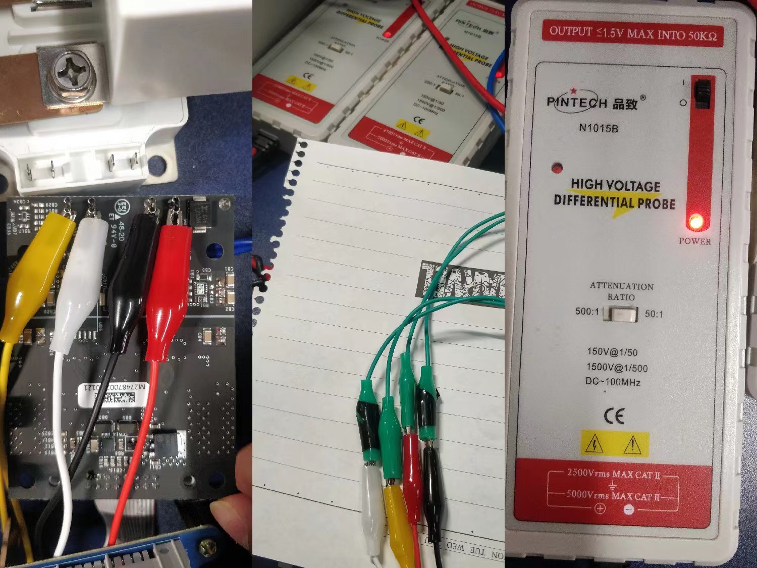
To start, it would be very helpful if you can share the probes that you're using to make these measurements and how you have them connected in the setup. A picture would be best if you don't mind to share. Also, have the probes been properly compensated?
Best Regards,
Austin C.
 1
1 -
Hi Austin C,
Thank you very much for your wise and effective advice.
At your suggestion, I re-tested the test with two probes, and the connection between the driver board and the probes is shown in Figure 1.
Figure 2 shows the drive test waveform of the high-voltage isolated differential probe, and the complementary drive waveform of the upper and lower tubes still has a serious oscillation problem.
Figure 3 shows the complementary drive waveform for the common probes(they have been properly compensated), and the waveform for the upper and lower tubes also has oscillation problems.
how should I solve these oscillation problems?
Thank you very much!
Best regard.
0 -
Hi ZhangYi,
Thank you for providing the extra pictures of your setup. After reviewing the images, I believe the oscillations are very likely caused by your probing configuration. While isolated probes are necessary to measure the high-side VGS signals in a converter, typical differential voltage probes do not have an adequate common-mode rejection ratio (CMRR) to accurately measure this small signal on top of the high-dv/dt drain-to-source voltage swing. Also the long cable extensions that you've added onto the probes will likely lead to increased noise and oscillations on your measurements.
To prove that the oscillations are not truly present in your system, I recommend that you operate the converter without any bus voltage applied and use a trusted single-ended passive probe to make the VGS measurements. If no voltage is applied to the bus, it is safe to operate the the gate drivers and control signals without the isolated probes just to verify the VGS waveform quality.
Please also check out the available references from Wolfspeed on recommended characterization techniques here:
PRD-07968: Wolfspeed WolfPACK™ Dynamic Performance Application Note
PRD-08333 Wolfspeed Module CIL Evaluation Kits User Guide
Austin C.
0 -
Hi, I hope that this answered your question. I will close this discussion for now but if you have a follow up question, please "Start a New Discussion" and we would be glad to support you further.
0


