Operating temperature range and Virtual-junction temperature vs. NTC resistance
1.Can you tell me the operating temperature range of the CRD300A12E-XM3?
There is no specification about it in the user manual.
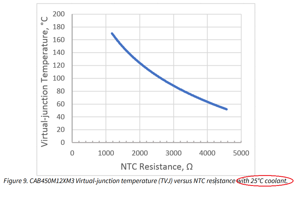
2.Can you provide the characteristic of the Figure9. in the user manual with the following coolant temperatures.
coolant temperature :50deg. , 75deg. , 100deg. , 125deg. , 150deg. (or 50deg. , 100deg. , 150deg.)
Regards,
JNagat
Comments
-
Thank you for your post, it has been approved and we will respond as soon as possible.
0 -
Hi JNagat,
The operating temperature range is determined by the maximum allowable power dissipation of the devices to keep the junction temperature below the rated value of 175 C. For example, at 300 kW, 25 C coolant, and 20 kHz, this would be roughly 4500 W. The output power derating curve vs. coolant temperature for 20 kHz is provided below.
We do not have full characterization of the virtual junction temperature vs. NTC resistance for different coolant temperatures. For more information regarding the NTC and how to use it, please refer to our new application note: PRD-08376: Thermal Characterization Methods and Applications.
Thanks,
Jonathan
0 -
Hello Jonathan,
Thank you for your answer.
For example, at 300 kW, 25 C coolant, and 20 kHz, this would be roughly 4500 W.
→May I know what the figure 4500w mean?
Regards,
JNagat
0 -
Hi JNagat,
4500 W is the maximum combined power dissipation of the three power modules in the inverter based on a conservative junction-to-liquid thermal impedance value of ~0.2 C/W (per switch position).
So (175 C - 25 C) / (0.2 C/W) = 750 W per switch position. So 4500 W (750 W x 6) for the inverter.
This is where that value comes from. The output power vs. coolant temperature plot that was shared above is based on this same calculation to demonstrate derating for increased coolant temperatures.
Thanks,
Jonathan
0


