SpeedFit™ Design Simulator
Simulate and evaluate the performance of SiC-based power circuits and determine the right SiC device in seconds.
Start a SimulationCAS350M12BM3 LTspice moduel Qustion. FullBridge_LLC simulation.

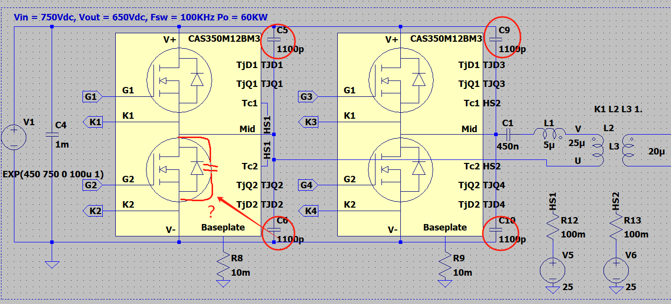
Recently, I have been using the power module CAS350M12BM3 to design a 60kW full-bridge LLC circuit. I downloaded the LTspice model and tried to simulate my circuit using LTspice. During the simulation, there were several questions that confused me:
1.Does the LTspice model of CAS350M12BM3 include the equivalent junction capacitance parameters between the D and S terminals of the device? At present, my method is to parallel a 1100pF capacitor (referring to the Coss on the Datasheet) between DS for simulation, but this will hinder the Mosfet from working in the ZVS state. Do I need this capacitor, and if so, how do I determine its capacity?
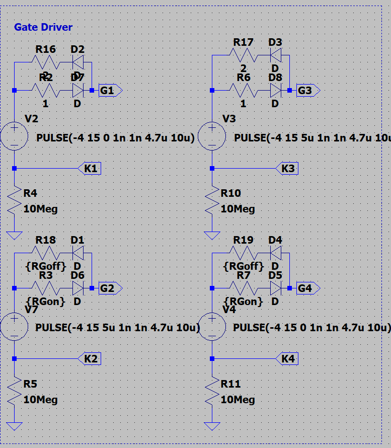
2.When I used the drive circuit in Figure 2 to drive the CAS350M12BM3, the gate voltage spike of the H MOS of the module was much larger than the L MOS. I don't understand what caused the problem. How do I adjust the circuit to eliminate spikes?