Thermal resistances for CAB016M12FM3 module
Hi,
I've already visited some forums here on the subject, but I'm still unsure about thermal resistance. We are using CAB016M12FM3 module.
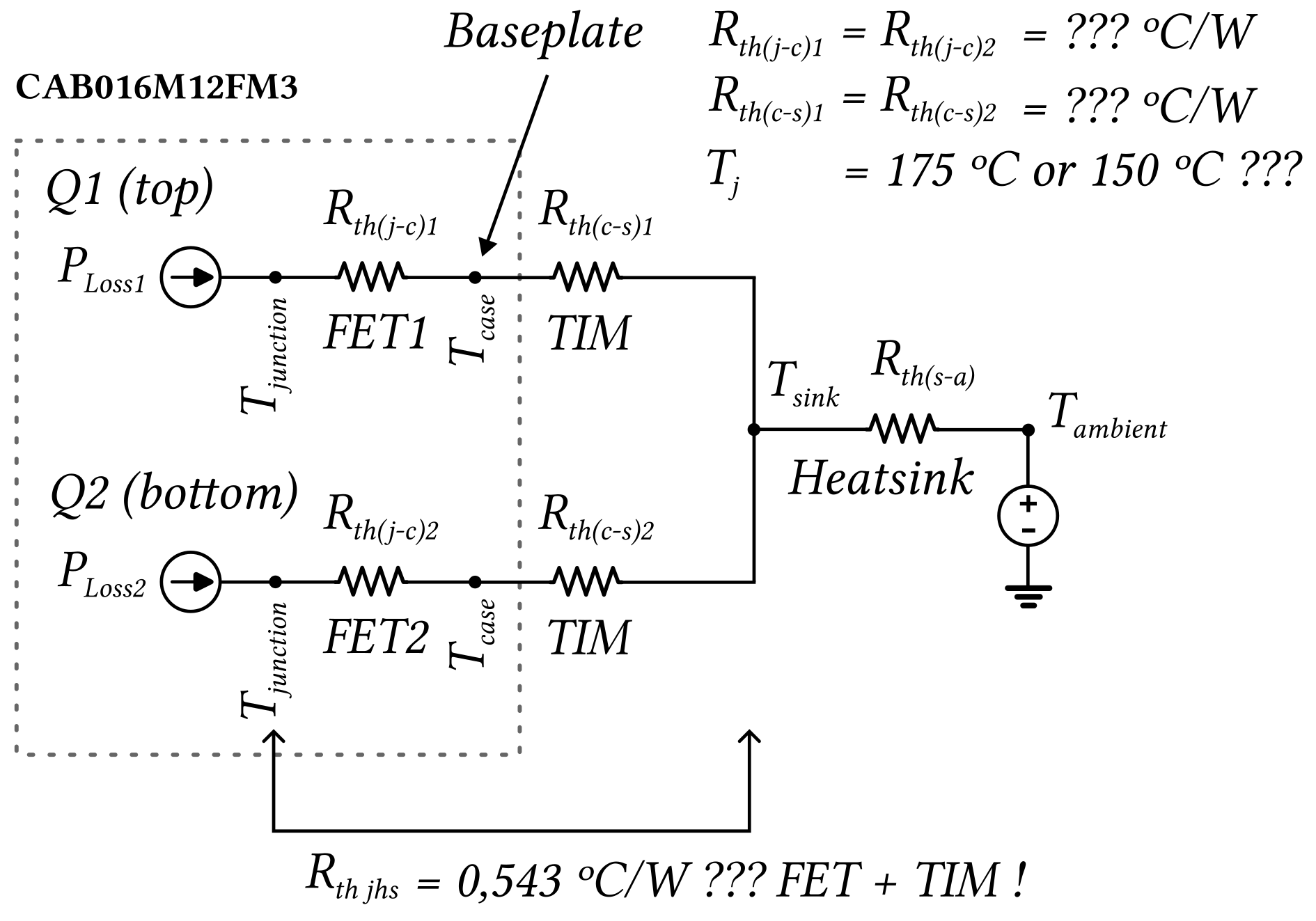
The thermal resistance reported in the datasheet already includes the FET plus the TIM material, correct?
I am sending an image to illustrate my application, which is the assembly of a module (only one) on a heatsink.
Could you tell me what the thermal resistance of the FET?
How can I calculate the thermal resistance of the TIM, for this module?
I would appreciate it if you helped me.
Thank you very much.
Comments
-
Thank you for your post, it has been approved and we will respond as soon as possible.
 1
1 -
Hi Robson,
Baseplate-less modules like Wolfpacks are expected to be attached to a coldplate with a suitable TIM. Our Wolfpack products with pre-applied TIM are thermally characterized using a Siemens T3Ster. The Rth_jh value depicted on Wolfpack datasheets is the sum of thermal impedances of the MOSFET switch position and high performance pre-applied TIM. A detailed explanation of the thermal resistance measurement procedure is provided here.
Since the thermal characterization of a Wolfpack module is always done with a high performance pre-applied TIM (PTM6000 series from Honeywell) , it is unfortunately not possible for us to provide the Rth values of the switch position and TIM material separately at the moment. We are investigating the possibility of providing you some data via simulations, however this might take some time.
Regards,
ArunA
 1
1 -
Hi ArunA,
Thank you for your feedback and additional documents.
For heat sink design, I will consider the thermal resistance Rth_JHS (Junction to Heatsink) from the datasheet as being the set of the FET plus the TIM (Thermal Interface Material) indicated here, according to the illustration I sent previously and in accordance with your clarifications.
For safety, I will apply a factor to prevent the junction temperature (Tj) from operating below the safety value, which is 150 ºC for this module (Virtual Junction Temperature).
Thanks,
Robson
0 -
Hi Robson,
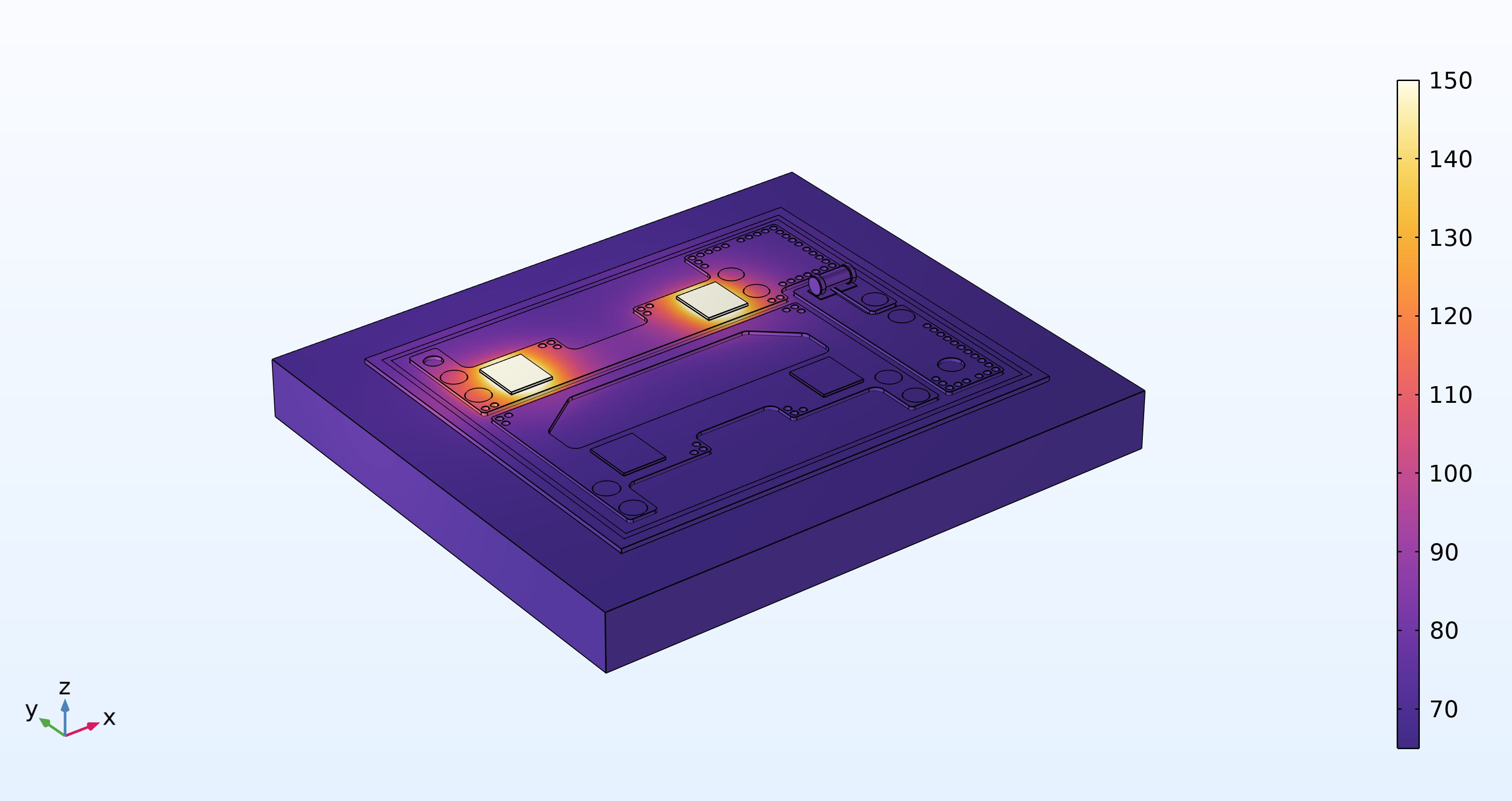
We don't have the ability to collect the data at this moment, but I ran a simulation in COMSOL for the CAB016M12FM3 module to get the Rth Estimates. We get a junction-to-heatsink (Rth_JHS) estimate of 0.54 K/W in simulation. This closely matches what is specified in the datasheet. Using the same simulation, we get a junction-to-case (Rth_JC) of about 0.31 K/W. We think the Rth_JC is correct but may be slightly lower than actual values, due to the simulation (Rth_JHS) being slightly higher than datasheet numbers.
Let me know if you have any additional questions !
Marshal Olimmah


 4
4 -
Hi Marshal Olimmah,
Thank you for your effort and your simulation provides very valuable data for my analysis.
This way, I can create a project very close to the practical conditions that the module offers. Furthermore, the importance of the indicated TIM (Thermal Interface Material) and its correct application are highlighted.
I am very grateful for your feedback.
Regards,
Robson
 1
1 -
Hi, I hope that this answered your question. If you have a follow up question, at a later date, please "Start a New Discussion"
0


