Turn-on gate voltage drop of SiC MOSFET
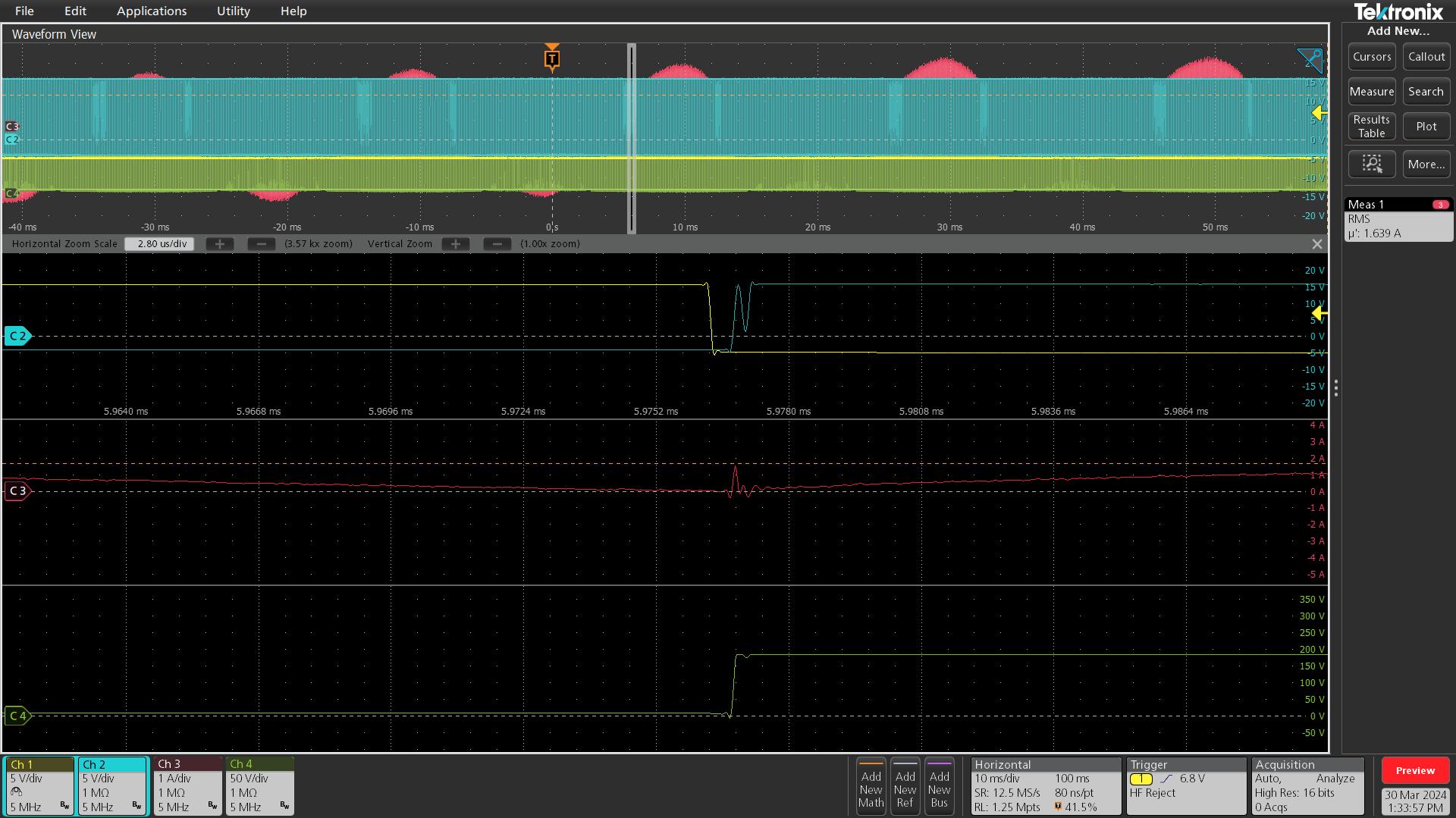
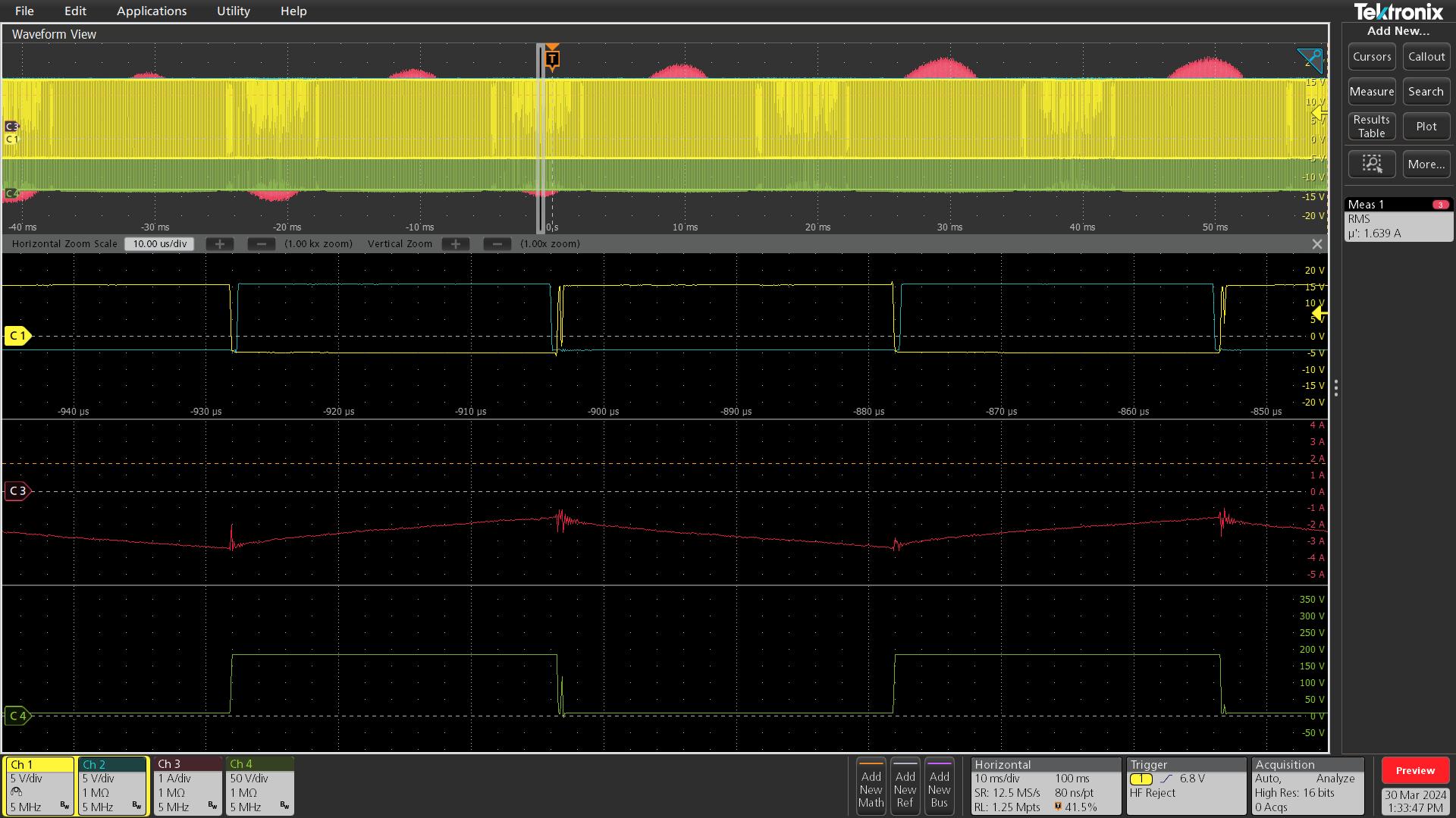
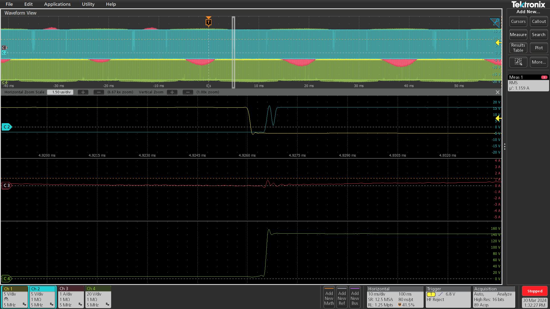
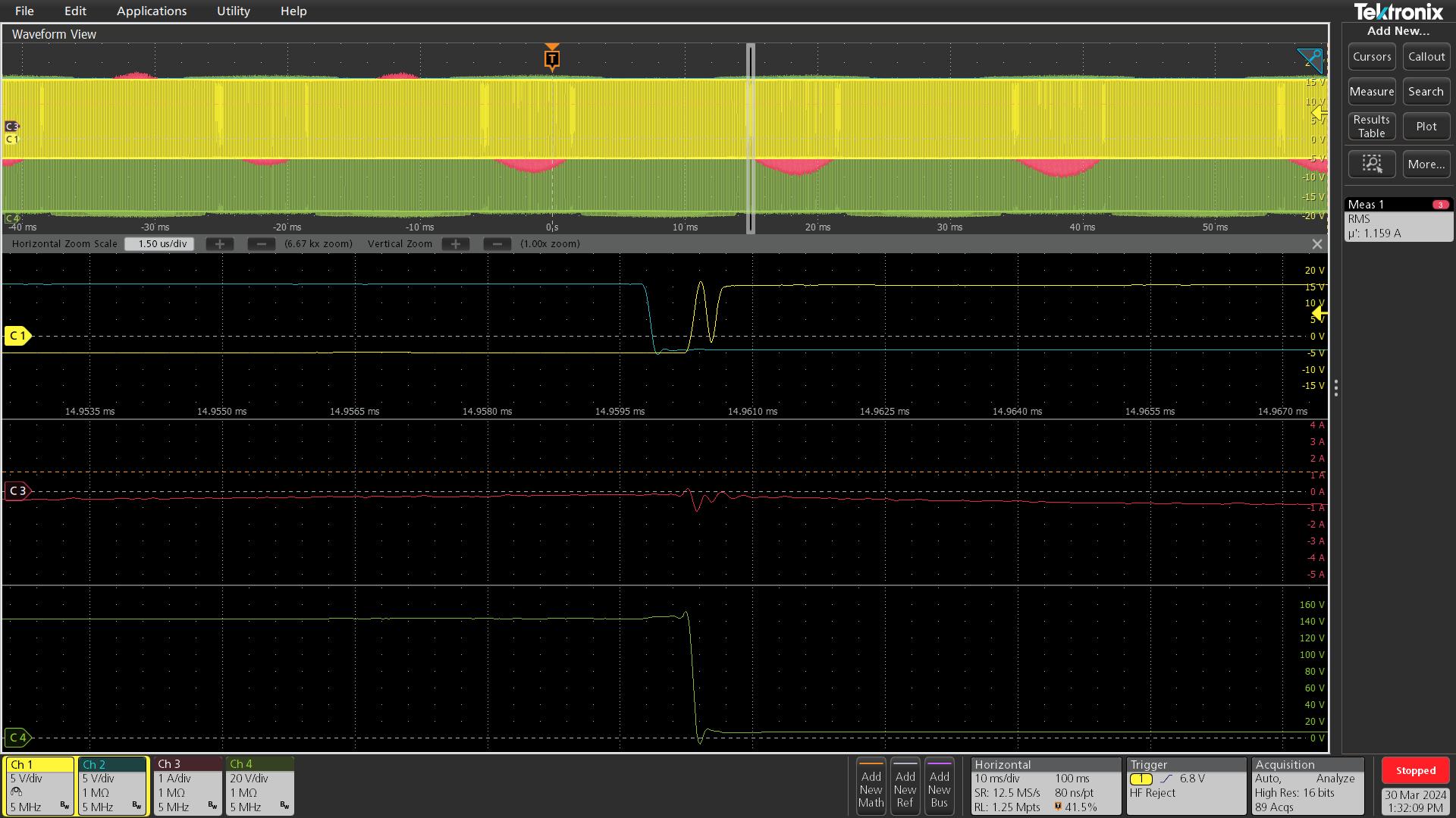
I have constructed an H-bridge inverter with only an inductive load for power cycling. One of the legs uses the SiC MOSFET C3M0060065D. However, I have observed gate voltage drop in both the upper and lower devices of this leg at turn-on. The turn-on gate resistance is 8 ohms. The following is the adopted driving scheme and the test results. So how can I solve this problem?Thanks!
The blue line is the Vgs of the upper device, the yellow line is the Vgs of the lower device, the red line is the inductive current, and the green line is the DC voltage.
Comments
-
Thank you for your post, it has been approved and we will respond as soon as possible.
0 -
Hello,
I simulated the circuit and noticed a dip in voltage V(n004,n008) (see attached image and simulation file in H_bridge.zip). This drop might stem from how the gate-source voltage is measured. This discrepency may arise from the method employed in measuring the gate-source voltage. Here are some things to consider
- The specific nodes selected for measurement
- The choice of probes utilised
- Potential parasitic elements within the measurement setup or gate-source loops.
If you can provide more details about these points, we might be able to assist you better.
Thanks!0 -
Hi, I hope that this answered your question. If it did, please click on "This question has been answered - Close Discussion" . If you have a follow up question, at a later date, please "Start a New Discussion"
0


