
SpeedFit™ Design Simulator
Simulate and evaluate the performance of SiC-based power circuits and determine the right SiC device in seconds.
Start a SimulationA question about the heat sink in the reference design CRD-06600FF065N-K

Jink
Contributor Level 1
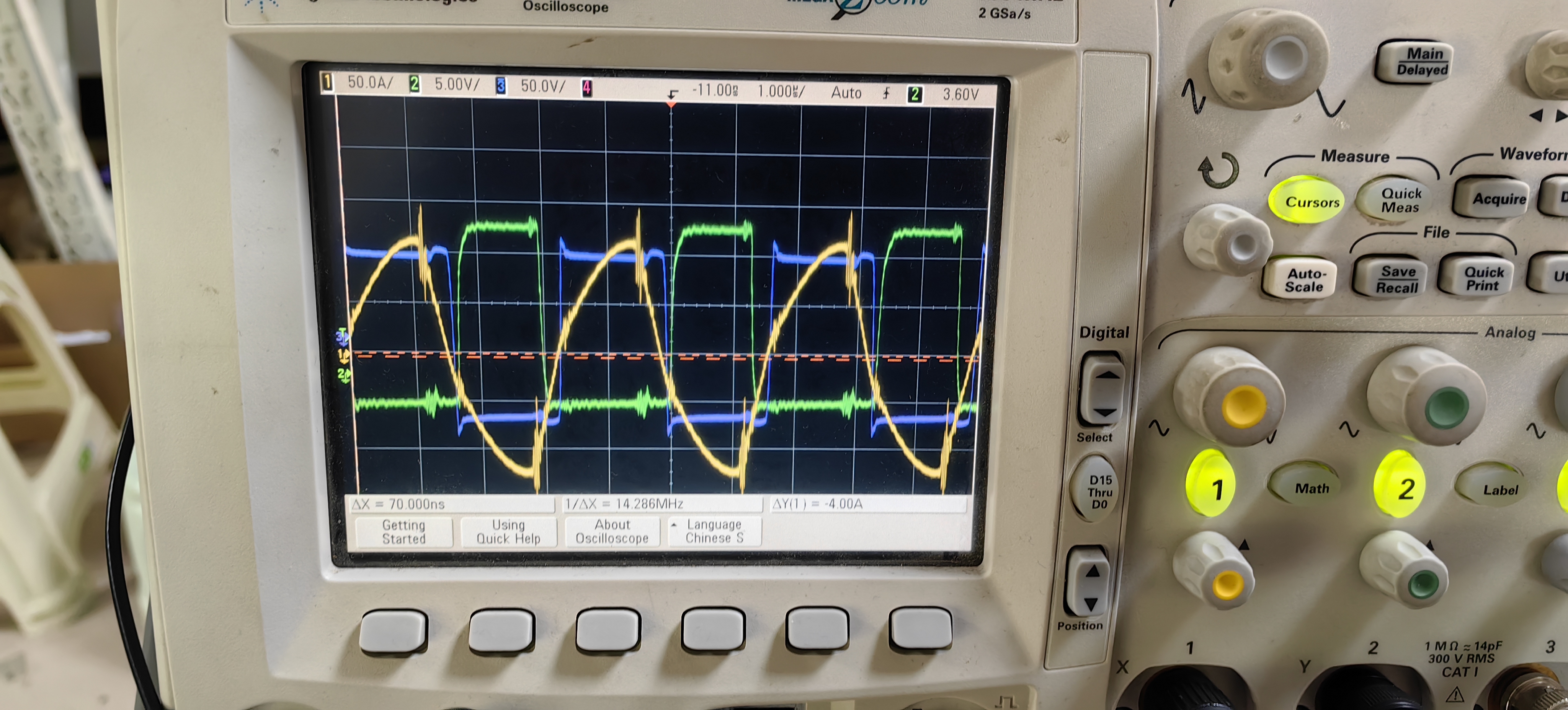
I was using the CRD-06600FF065N-K PCB file for the design and found that the CLLC converter was in the overresonant state with a lot of electromagnetic radiation, which had interfered with the current sampling. I found that there is a high-frequency current oscillation when the switch is operated through the current transformer, but there is no abnormality in the voltage at the midpoint of the bridge arm. I didn't use a fully enclosed radiator for heat dissipation, I don't know if that's the reason?

Tagged:
0