THE FAULT OF CGD1700HB2M-UNA
Hello.
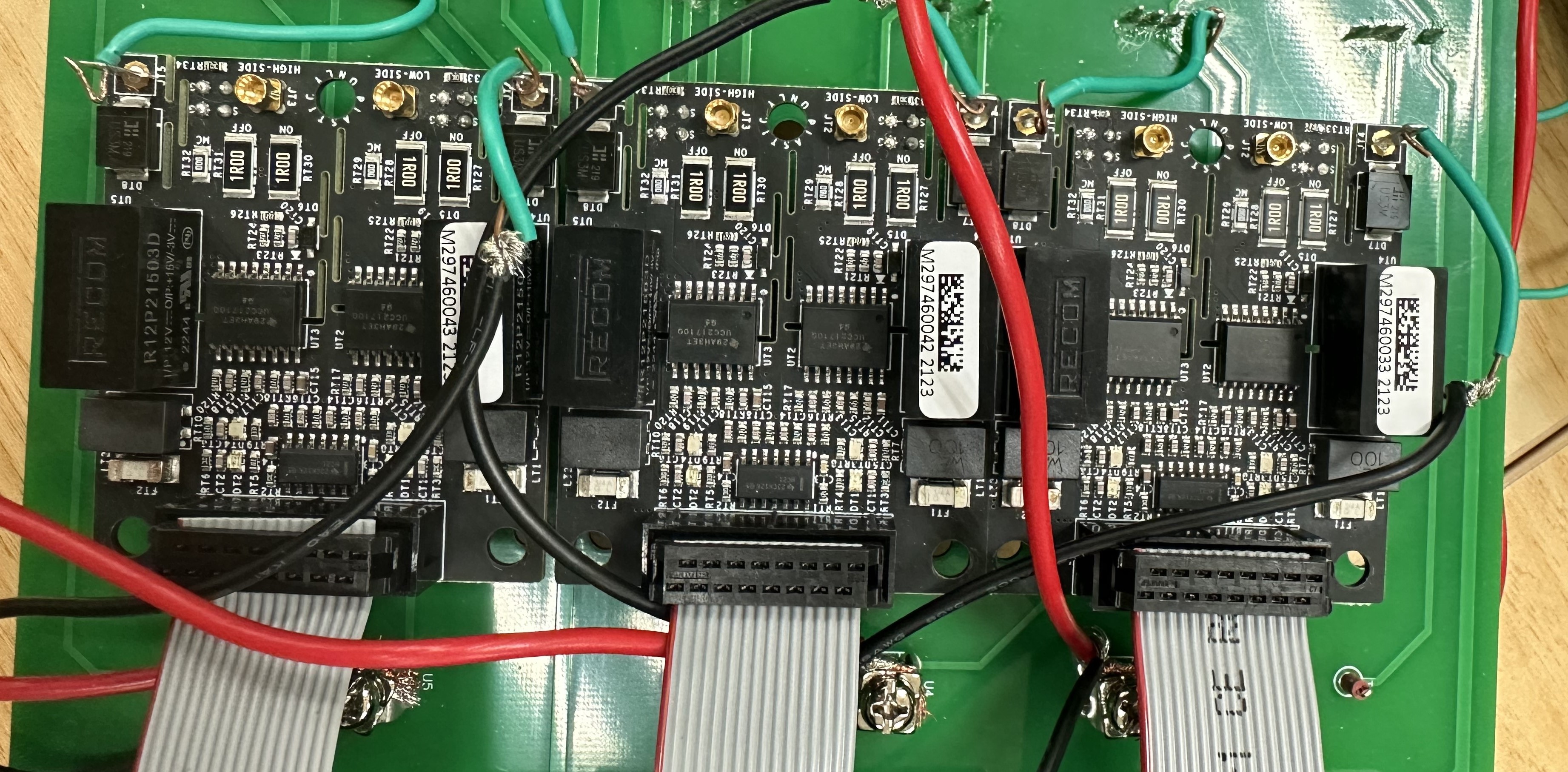
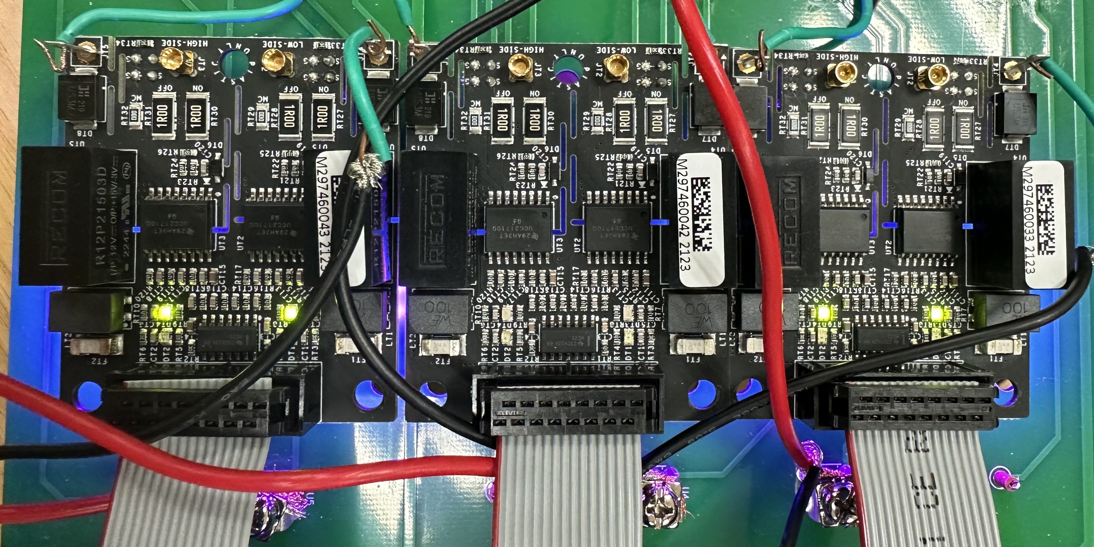
I output six pwms through the microcontroller (STM32F103ZET6), and accordingly connect the complementary 2 to the input (J1) of the corresponding differential transceiver (CGD12HB00D) respectively, and then give it from the output (J2) of the differential transceiver to the gate driver board (CGD1700HB2M-UNA), which results in the power supply of the gate driver power supply indicators (DT3 and DT4) go out, as shown in Figure 1, but disconnecting any of the three gate driver input ports from the differential transceiver immediately restores the power indicators of the remaining two, as shown in Figure 2. What is the cause of this phenomenon and what is the solution. Very much looking forward to your reply.
Figure 1
Figure 2
Comments
-
Thank you for your post, it has been approved and we will respond as soon as possible.
0 -
Hi MOONLIGHT,
What is the load that the CGD1700HB2M-UNA is driving and what is the commanded switching frequency? Have you calculated the expected gate driver power requirement for your load & operating frequency to confirm it is less than 2 W?
Best Regards,
Austin C.
0 -
Hello Austin C,
my problem has been solved, it is true that the power of the gate driver is not enough, it has been adjusted and it can work normally. Thank you very much for your answers.There are temperature terminals on the gate driver that can be measured. If I want to estimate the junction temperature of a power device, do I need to connect an external NTC resistor, can I directly connect it to the C3M0021120K body diode? Is there a better way to estimate the junction temperature of power devices in a three-phase inverter? I look forward to hearing from you.
0 -
Hi MOONLIGHT,
The CGD1700HB2M-UNA gate driver board was designed to be connected to an external NTC resistor to monitor a temperature. Generally this is used with one of Wolfspeed's power modules featuring a built-in NTC resistor, but the gate driver board could be used to monitor a separate thermistor as well. The CGD1700HB2M-UNA's temperature input should not be used with a SiC MOSFET's body diode.
Generally a PLECS model is utilized to predict the junction temperatures of the MOSFETs during operation. Before the PLECS model can be properly utilized, an accurate thermal model of the system is necessary to estimate the junction temperature. Please refer to the guidance provided in the Application Note here to measure the thermal performance of your system including the heatsink, thermal interface material, and module or discrete device.Thanks,
Austin C.
0 -
Hello Austin C,
Thank you very much for your answer.
0


