the pspice model file of CAS480M12HM3
Hello, now I need a model of -40℃~175℃ for CAS480M12HM3, but the temperature range of pspice model provided on the official website is 25℃~175℃. I plan to build it on the basis of the existing model of pspice, but I have some problems in understanding the existing model:
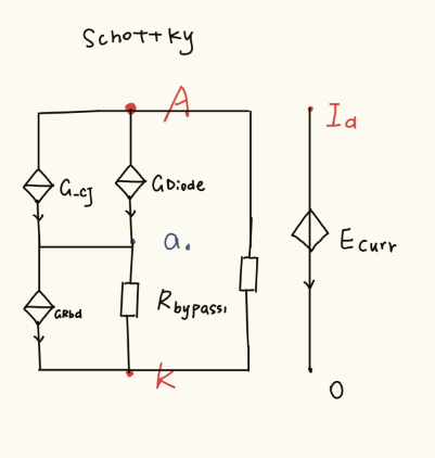
Is the schottky circuit diagram of mosfet drawn by me according to the existing model correct? If not, where is the error?
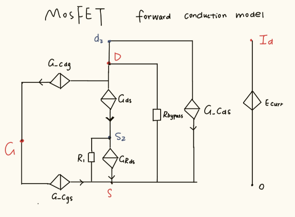
1.Do Gds and GRds represent changes caused by changes in threshold voltage and on-resistance respectively in the MOSFET forward circuit diagram? If not, what do those two stand for?
2.What is the role of R1 and Rbypass in the MOSFET forward circuit diagram?
3.Now I want to expand the temperature range to -40℃. What changes do I need to make if I want to modify the existing model?
Looking forward to your reply
Comments
-
Thank you for your post, it has been approved and we will respond as soon as possible.
0 -
Hi Emma,
I believe I've answered some of these questions on your other post.
Your drawing of the Schottky diode netlist looks reasonable. Rbypass1 and Rbypass2 are implemented to solve only convergence and floating node errors.
Ecurr and I_a exist for power calculations, so you can ignore those.
The combination of GRbd and GDiode make up the conduction branch. GRbd is functionally a resistance, while GDiode is the primary energy source. The diode model is simply a Schokley diode equation in series with a resistance. G_cj then is just the parasitic capacitance across the diode (but GRbd is placed in series for better computation).
To modify your model for operation at -40C, you will want to adjust many of the functions with a 'Tj' dependence. Let me explain each for you. Of course, you don't have to adjust all of these - you can pick and choose based on what you think is important. I'm not sure how you plan on tackling this, but keep in mind that it can be tricky to develop fitting algorithms that can do a current source and resistance in combination. I recommend numerical approximation techniques. Feel free to reach out if you run into this challenge.
For forward conduction
The forward conduction model's temp-dependent characteristics are driven by .func RTJ(Tj) and .func VthFwd(Tj). RTJ represents an Rds(on) shift, and VthFwd represents a voltage shift. To expand the temperature dependence range, you'll need to add more entries to these functions to reflect the resistance/Vth change down to -40C. SPICE will linearly interpolate between entries.
For reverse conduction
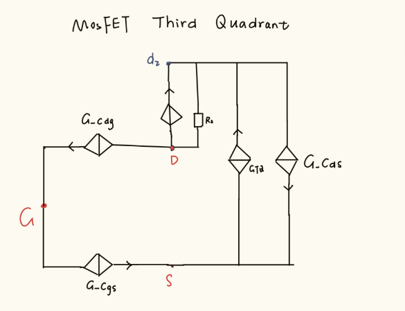
Same as for the forward conduction, but now you'll need to look at RdBD and VthBD. This one may be a bit tricky, and I'm not sure how well it will work. Since this part has a Schottky diode, you can likely ignore it. (NOTE: ON state reverse conduction is handled by the forward conduction model, so by adjusting the Rds(on) and Vth shift for the forward conduction, you will be changing the reverse conduction when the MOSFET is ON. So, for example, in synchronous switching with the device ON and reverse conducting).
For reverse recovery
The tau and TM parameters affect the reverse recovery behavior of the part. The current 25C parameters in the model correspond to basically no reverse recovery.
For the Schottky diode
You'll need to adjust nn and Rs. This one should be pretty simple, but again requires some care when developing your fitting function with the resistor + current source combination.
Hope this helps,
Brian
 0
0 -
Hi, I hope that this answered your question. I will close this discussion for now but if you have a follow up question, please "Start a New Discussion" and we would be glad to support you further.
0


