Pulse Width and Pulse Period Typical Value for the I-V characteristics of SiC MOSFET
Hi,
I am analyzing the data sheet of Silicon Carbide Power MOSFET "C3M0015065K". I am particularly interested in Diagram 1: Output Characteristics TJ = -40 °C. I believe these I-V characteristics have been measured with the pulsed gate voltage. I want to know what is the pulse with and the pulsed period of the gate voltage applied is?
Comments
-
Thank you for your post, it has been approved and we will respond as soon as possible.
0 -
Hello Hassan ,
The pulse delay is 0s and the pulse width is 1ms for the gate voltage applied.
0 -
Hi TBhatia,
Thank you for your response. Really appreciate it. Regarding the pulse delay, I would like to mention my understanding. The pulse delay is the delay between each consecutive gate pulse to get the whole I-V curve. I believe the curve tracer that Wolfspeed uses, incorporates the pulse delay parameter to get the whole I-V characteristics. Can you just confirm that if the pulse delay is incorporated between consecutive gate pulse?
Moreover, are the pulse delay and pulse width is same for the Figure 2?
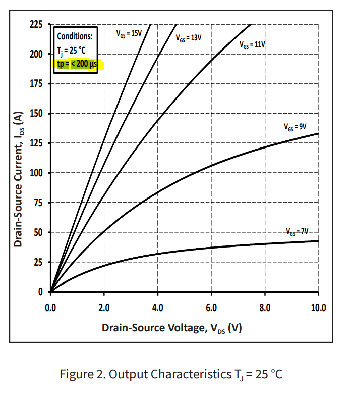
Lastly, according to Figure 1 and Figure 2 tp<200us. What is this parameter? Is it related to pulse width of the gate? Attached is the figure 2 for your information.
0 -
Hello Wolfspeed,
Any update on this question.Regards,
Hassan
0 -
Hello Hassan,
- The pulse delay mentioned is incorporated between consecutive gate pulse.
- The pulse delay and pulse width are the same for Figure 2
- In figure 1 and 2 the pulse width mentioned is the pulse width of the voltage applied (Vds) to take the current flowing through the device (Ids) measurement. For this device, Vds is swept from 0 to 10V to measure Ids(A). The upper value of Ids(A) is set to 225A so for Vgs= 11, 13 and 15V, you see that the curve stops before Vds reaches 10V but for Vgs= 7 and 9 V, it reaches the Vds limit of 10V first.
Let me know if this answers your questions!
0 -
Hello TBhatia,
Thank you for clarification. I think I need more clarification:- If the pulse delay mentioned is incorporated between consecutive gate pulse, what is the value of the pulse delay between consecutive gate pulse? You mentioned that being 0s. It means that there is no delay between consecutive gate pulse. Rather the gate voltage is constantly provided to the MOSFET gate terminal. On the other hand the drain voltage is provided as a pulse with a pulse width of <200us but again what is the delay between the consecutive drain voltage pulse?
Appreciate your response.
Regards,
Hassan
0 -
Hello Hassan,
The pulse delay between drain voltage pulses is 50us.
0 -
Hi TBhatia,
Thank you very much for more information this makes more sense to me. Let me summarize that to consolidate my understanding and then I have few more questions:
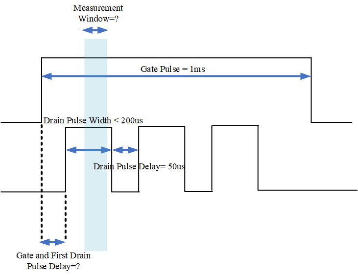
The Figure 1 and Figure 2 which are the I-V characteristics of the MOSFET are obtained by applying a gate pulse of 1ms width. The drain pulse width should be less 200us and the delay between consecutive drain pulse is 50us.
- Now I think there will be a little delay between the turning on of the gate pulse and first drain pulse, so that the gate voltage gets stabilized before applying the drain pulse. If this the case I would like to know the value of this delay time. Can you please tell me?
- There will be a little delay between the turning on of the drain pulse and the start of the measurement. Generally this delay is incorporated to ensure the measurement in the stable current and voltage region. Can you please provide how much this delay is provided?
I have added a simple pulse of gate and drain figure to show all these times. Appreciate your response.
Regards,
Hassan
0 -
Hi TBhatia,
Appreciate your response.
Regards,
Hassan
0 -
Hello Hassan,
- Pulse delay is 50us (Before any drain pulse, the delay is set to 50us)
- The measurement window is also 50us
Thank you!
 1
1


