
SpeedFit™ Design Simulator
Simulate and evaluate the performance of SiC-based power circuits and determine the right SiC device in seconds.
Start a SimulationChange the driver board parameters

Hello, I met some difficulties when selecting the type of drive board. I want to drive the CAS480M12HM3 half-bridge module, and I chose CGD1700HB3P-HM3, but I still need to change the drive voltage and drive resistance on the drive board to explore the influence of the drive loop parameters on the switching characteristics. How can I change the driving voltage and driving resistance?
Comments
-
Thank you for your post, it has been approved and we will respond as soon as possible.
0 -
Emma,
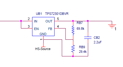
The design files for the CGD1700HB3P-HM3 can be downloaded here. The negative drive voltage can be adjusted with the linear regulators (UT10 and UB1) by adjusting RB9 and RT20.
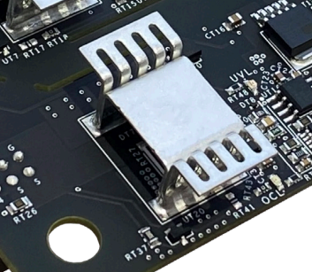
The turn on and turn off gate drive resistors (RT2, RT3, RT27, RT28) can be changed to adjust the gate drive resistance after removing the heatsink.
Adjustment of the positive drive voltage is not easily achievable.
-Paul0 -
Thank you for your answer. But I need to study the effect of drive voltage on SiC MOSFET loss. How can I change the positive drive voltage?
Looking forward to your reply, thank you0 -
Emma,
It is not designed to adjust the positive voltage rail. Additional circuitry is required to regulate the voltage down. The CGD1700HB2P-BM3 has the pads for a LDO to tune the gate drive voltage. If you have Altium you could change the pin headers in the design and use that driver instead?
There is not an easy solution currently available.Thanks,
-Paul
0 -
Hi, I hope that this answered your question. I will close this discussion for now but if you have a follow up question, please "Start a New Discussion" and we would be glad to support you further.
0