SpeedFit™ Design Simulator
Simulate and evaluate the performance of SiC-based power circuits and determine the right SiC device in seconds.
Start a SimulationSupport of motherboard MOD-MB-HB-0900V-40A with TI control card TMDSCNCD280039C for MPPT Boost

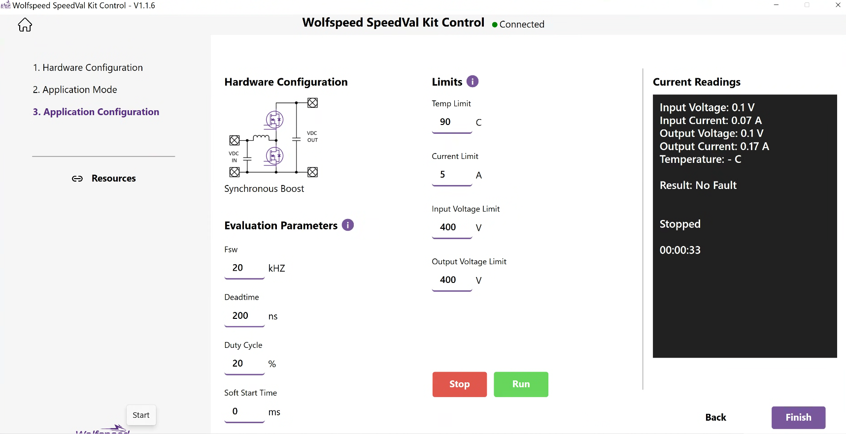
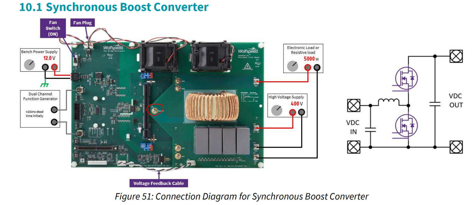
We have TI control card TMDSCNCD280039C for the full motherboard MOD-MB-HB-0900V-40A. Unfortunately, the Speedval Graphical User Interface (GUI) not provide the desired output voltage and current. We just configured in Synchronouse Boost Mode.
Comments
-
Thank you for your post, it has been approved and we will respond as soon as possible.
0 -
Hello,
Can you provide some additional details? What is your input voltage that you are supplying to the boost board? What happens when you click "Run"? Does it boost to a different voltage than expected, or does it not do anything?
0 -
Hello,
Yea, my input supply voltage is 120V. When I click "Run," the fan is working. However, their is no output voltage and not temp. I also checked with an oscilloscope; their is nothing. The GUI is connected. I have used a TI-controlled card and flashed it successfully.0 -
Hello,
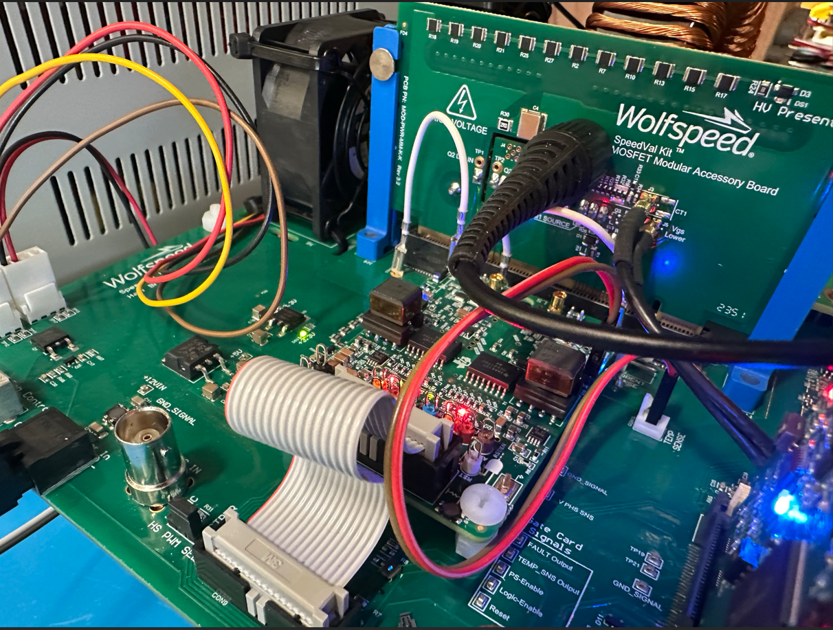
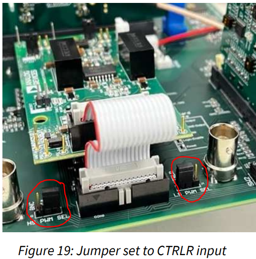
Is the GUI reporting 120V on the input and output? Even without the PWMs operating, the the output should match the input for a boost configuration. Are there any faults being reported on the GUI, or indicated by the LEDs on the gate driver? If so, try clearing them using the reset button on the motherboard. Are both both jumpers installed in the correct position to utilize the PWM signals coming from the controller as shown below?
 0
0 -
The GUI reports 120 on the input side, but not on the output. The first time, there was a red LED (fault), which we fixed. We reset the motherboard, but we still did not get any output results, either on the GUI or the oscilloscope. The jumpers are installed correctly.
Here is our com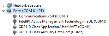 0
0 -
Hello,
Can you double check the setup? Even without the MOSFETs switching, the input voltage should equal the output voltage for a boost converter.
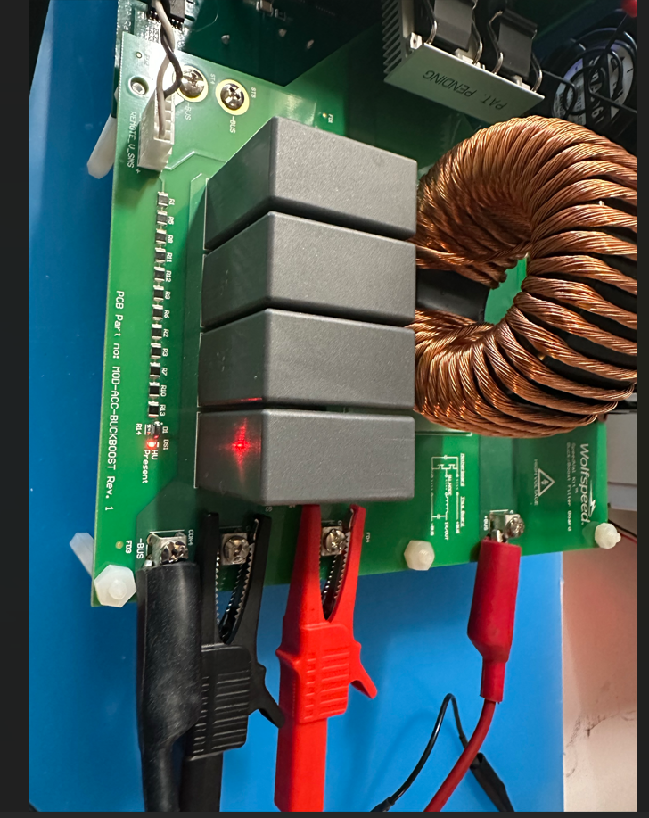
- Unplug the MOSFET power card and use a digital multimeter to verify continuity through the inductor by measuring between the CON3 screw terminal on the boost board and ST3 plated hole attaching the boost board to the switch node on the motherboard.
- Ensure the 5 screws attaching the boost board to the motherboard are fully installed, including the one below the heatsink on the MOSFET power card.
- Ensure the MOSFET card is fully seated into the card edge connector
- Without any voltage applied to the board, use a digital multimeter to perform a diode check on the MOSFET both body diodes. Lower diode: Red lead on CON4, black lead on CON3 on boost board. Upper diode: Red lead on CON3, black lead on CON1 on boost board.
Please let me know if any of these verifications fail.
 0
0 -
Hi, I hope that this answered your question. I will close this discussion for now but if you have a follow up question, please "Start a New Discussion" and we would be glad to support you further.
0