SpeedFit™ Design Simulator
Simulate and evaluate the performance of SiC-based power circuits and determine the right SiC device in seconds.
Start a SimulationHow to derate the RBSOA of the CAB760M12HM3 module

Good morning, how can I determine the maximum current and voltage that a single mosfet can withstand during turn-off? How does this depend on the turn-off speed? I tried to analyze it using the RBSOA graph, but I don't know how to perform derating while also taking temperature into account.
Comments
-
Thank you for your post, it has been approved and we will respond as soon as possible.
0 -
Hi fra,
Most SiC MOSFET-based power modules are not intended for use in the linear region. As these devices were designed to enable fast transients to minimize switching loss, they have high transconductance and are not stable below the ZTC point, which is typically around VGS = 10 - 12 V. Below the ZTC point and above the threshold voltage, in the linear region, the MOSFETs will experience a positive temperature coefficient with respect to current resulting in the device current rising while VGS is held constant, which leads to thermal runaway.
It is recommended that the CAB760M12HM3 module be turned on and off via the drive voltages listed on the datasheet (+15 V and -4 V) with a gate resistance that is stated on the datasheet (< 10 Ω) to ensure stability of the device.
Best Regards,
Austin C.
0 -
Thanks for your response. I'm using this module for a research project on the implementation of an SSPC. If the module is used as a switch and operates at 90 degrees, what is the maximum current it can interrupt? I would like to understand how to use the RBSOA graph.
0 -
Hi fra,
You can use the information in the transient thermal impedance plot from the datasheet to calculate the maximum pulse current that the module can handle for various pulse widths. The simplest way to perform this evaluation is with the LTspice model for the CAB760M12HM3 where you can monitor the junction temperature and apply various current pulses to the module. I also recommend reviewing the new transient thermal model user guide below.
Power Module RC Thermal Models User Guide
Best Regards,
Austin C.
0 -
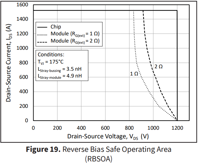
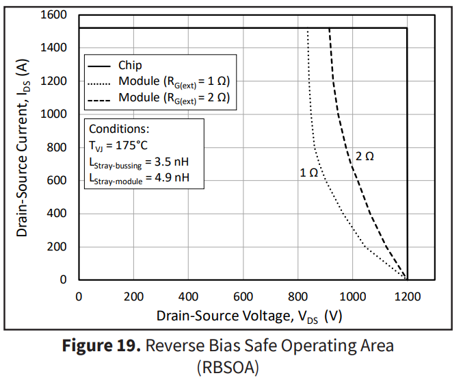
To prevent the component from degrading, an appropriate derating must be applied. To safely turn off the mosfet, the RBSOA graph (shown here) should be used, which refers to a junction temperature of 175 degrees. I would like to know how this graph changes if I want to keep the junction at a lower temperature and its dependence on the case temperature.
0 -
Hi fra,
To start, let me explain what is portrayed in this plot as it differs from some of our competitors' RBSOA plots. The data is acquired via double-pulse testing performed on the CAB760M12HM3 using the dynamic evaluation kit for the HM3 and our reference gate driver, the CGD1700HB3P-HM3. The voltage overshoot observed during MOSFET turn-off and diode turn-off (reverse recovery) is measured, and the difference between the device's voltage rating (1200 V) and the observed overshoot voltage is computed. This difference is then utilized to plot the maximum achievable bus voltage for a given operating condition and is plotted in Figure 19. So the plot contains the maximum bus voltage that could be realized for a given RG using our evaluation kit and reference gate driver.
For example, when operating with an RG-EXT of 2 Ω, at a current of 700 A, and at TJ = 175°C, the maximum bus voltage that could be run in your system and remain under the device's voltage rating is 1,000 V.
The voltage measurement points are from kelvin-source of the low-side to the kelvin-source of the high-side, so the inductance of the power leads is not included in the measurement. In this test, a hot plate is utilized to heat the junction temperature to the desired set point, so the case and the junction are both approximately 175°C.
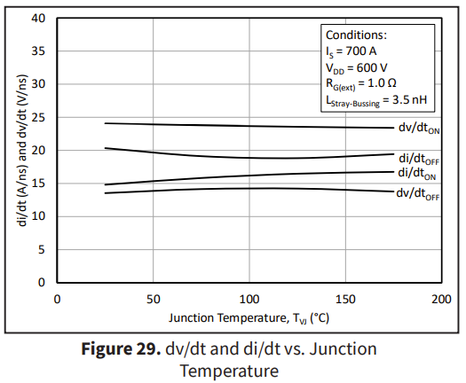
To determine how the voltage overshoot will change with junction temperature, the best practice would be to acquire a sample and perform double-pulse testing across temperature and any other variables of interest, but you can get an initial idea from the di/dt provided in Figure 29 (V = L*di/dt). As shown below, the di/dt across temperature is very stable for the CAB760M12HM3, so the resulting voltage overshoot and therefore the RBSOA plot would not be expected to change across temperature.
Best Regards,
Austin C.
0 -
Hi, I hope that this answered your question. I will close this discussion for now but if you have a follow up question, please "Start a New Discussion" and we would be glad to support you further.
0