
SpeedFit™ Design Simulator
Simulate and evaluate the performance of SiC-based power circuits and determine the right SiC device in seconds.
Start a SimulationDebugging Analog Measurements on CRD25AD12N

Hello,
Not sure if this topic is appropriate for this forum, but I purchased a CRD25DA12N-FMC and have tried running the firmware provided multiple times. I was able to generate expected sinusoidal waveforms on the power side of things, but using the debugging I am watching variables like VoltageMsgData[6]/VoltageMsgData[7], which do not seem to correlate with the physical system.
(e.g., VoltageMsgData[6]/VoltageMsgData[7] do not really change if I apply 0V, 50V, or 100V, even though I am expecting
- VoltageMsgData[6] (high byte) ≈ 0x00 (0)
- VoltageMsgData[7] (low byte) ≈ 0x64 (100)
for 100Vdc applied)
Any ideas what could be causing this?
Comments
-
Thank you for your post, it has been approved and we will respond as soon as possible.
0 -
For reference, my board serial number is F2540-A001 and the PCB itself is labeled:
CRD25DA12N-FMC v2.0 09/2024
I am now noticing differences between the physical board I have and schematic/design files I downloaded (dated v1.1 07/2023).
I am wondering if the pcb design has changed? And should I be referring to a new schematic and possible firmware as well?
Thanks in advance!
0 -
Hello tjdonne,
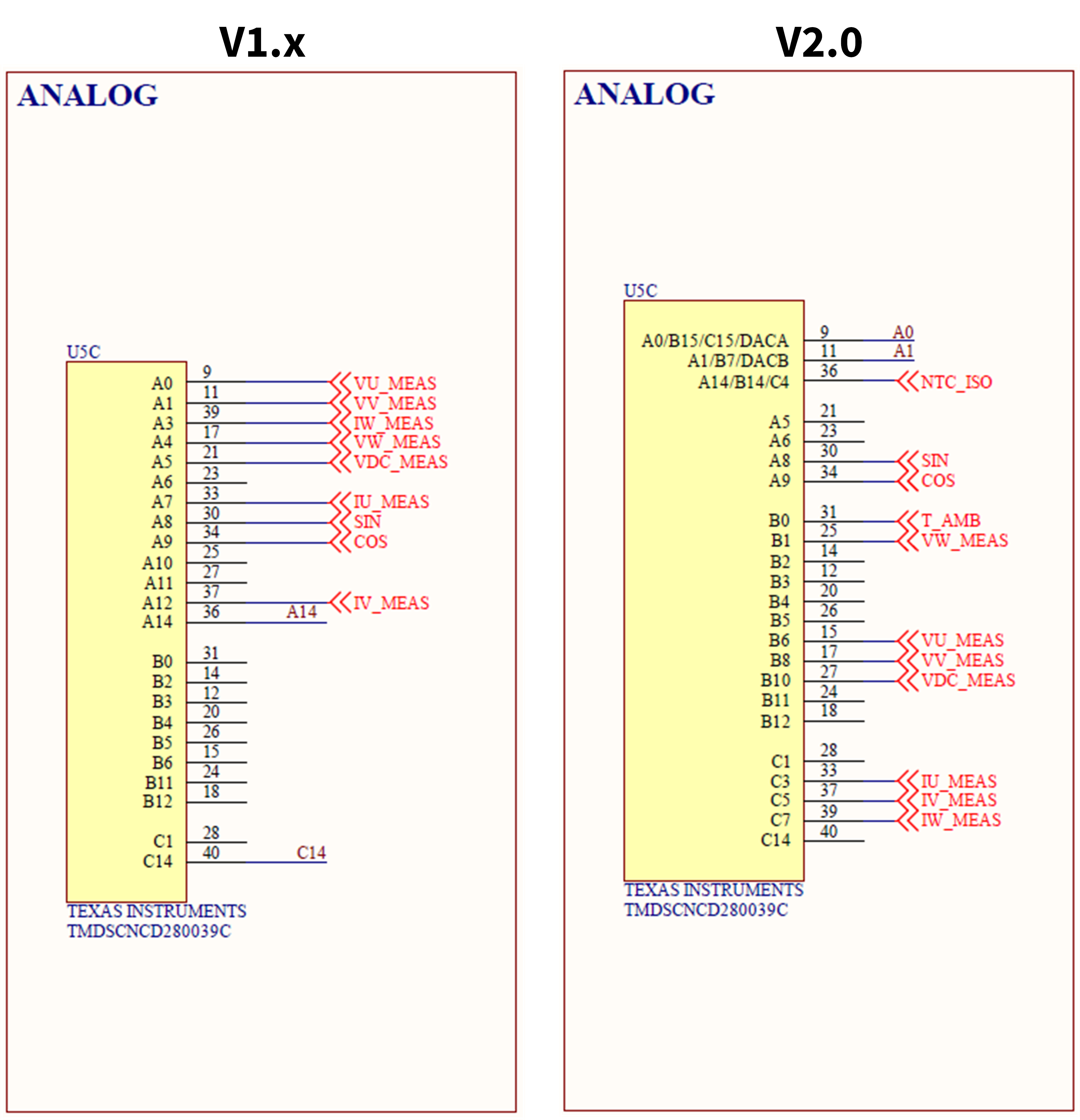
Your issue sounds like it is related to upgrades we made to the V2.0 hardware. Several improvements were introduced in the V2.0 hardware based on additional internal testing and customer feedback. Most of these changes are backwards compatible with the firmware. However, the VDC pin mapping is not backwards compatible. The pin mapping of the VDC was swapped so that the voltages are all grouped on the same analog-to-digital converter (ADC) channel and so that the voltage & current measurements were on different ADC channels. This enables more flexibility with using the ADC post-processing blocks (PPB) that are built into the controlCARD and Code Composer Studio. The gate driver modulation was not affected by the updated hardware which would explain why the sinusoidal outputs are still working properly.
I attached the updated firmware which fixes the pin mapping (this is the firmware that ships on the units). The new firmware (V2.0.0) transitions to using the SysConfig tool in CCS which is the current "best practice" for C2000 programming recommended by Texas Instruments. I also attached the updated schematic and provided a picture of the ADC differences below. We have an active request in for the website to get updated, so I expect the firmware and design files download links to be updated soon.
Thanks,
Chris N.
0 -
Hello tjdonne,
My recommendation is to transition to the v2.0.0 firmware, as I mentioned in my previous post. However, if you have already put time into the v1.0.0 firmware (such as making customization or feeling more comfortable with the legacy coding approach), I attached a document which details the expected updates required to measure the new VDC pin. Please note I have not been able to test these edits on the hardware yet, so some minor tweaking might be required.
Thanks,
Chris N.
0 -
Thank you very much!
It took me longer than I care to admit to notice the v1 vs v2 :), but in any case this is exactly what I needed and thank you for the quick support!0 -
Hello tjdonne,
Following up on my previous message, all the design files and firmware download links have been updated on the webpage to include the version 2 details. These downloads are currently the same as the ones I provided above. For future readers of this forum, I recommend downloading the design/firmware files directly from the website landing page (rather than from the above download links) in case any further hardware/firmware updates are released.
Thanks,
Chris N.
0