
SpeedFit™ Design Simulator
Simulate and evaluate the performance of SiC-based power circuits and determine the right SiC device in seconds.
Start a SimulationClarification on CAB450M12XM3 half-bridge MOSFET Module

Hello,
I am developing an H-bridge using CAB450M12XM3 half-bridge MOSFET units for a high-current application. Along with this, we are planning to use the CRD300DA12E-XM3 inverter as a traction inverter to drive our dynamometer setup.
I am currently working on the PCB design and would like to know whether Wolfspeed provides the symbol and footprint for the CAB450M12XM3 half-bridge module. Additionally, I plan to use the CGD1200HB2P-XM3 gate driver module directly with the MOSFET module.
In the meantime, could you please provide the CRD300DA12E-XM3 inverter Altium design file? Having this would help me understand how the power modules are mounted and would be very useful in designing the full-bridge layout.
Thank you very much for your support.
Best Regards
Sachith
Comments
-
Thank you for your post, it has been approved and we will respond as soon as possible.
0 -
Hello Sachith,
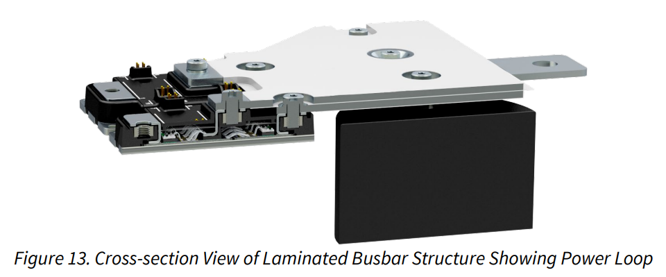
Thank for your interest in the XM product line and reference designs. XM power modules are typically integrated into systems using laminated bussing instead of printed circuit boards (PCBs) to take advantage of the high ampacity ratings of XM power modules. The CRD300DA12E-XM3 reference design that you identified also uses laminated bussing, as shown in Figure 13 of the user guide and repeated below. I provided some additional information and a STEP file (attached) of the bussing here. PCBs can still be used for designs, though you have to be more critical of the thermals of the boards.
If you decide to use a PCB design, I attached several files to help you get started. First, I attached the control board PCBs for the CRD300DA12E-XM3 reference design. These designs were originally created using OrCAD/Allegro, but I converted them to Altium for you to view. Second, I attached the design files for the KIT-CRD-CIL17N-XM evaluation board which is a PCB design used for dynamic characterization of XM power modules. This board was also originally developed in OrCAD/Allegro, but I included the Altium converted files. Third, I attached the paralleling PCB used for PRD-08911 which includes three XM power modules and was developed in Altium. The module symbol and footprint can be extracted from this design. Finally, I attached the spacers used for attaching XM power modules to PCBs since the XM modules include a difference in terminal height in the z-direction which is advantageous for laminated bussing. Without the spacers on PCBs though, the XM will not sit flush to the PCB.
Thanks,
Chris N.
0 -
Hi Chris,
Thank you for the valuable information.
I have one clarification. I found a document describing the inline and cross pinout configurations for the XM module, along with the corresponding recommended gate drivers. Based on my understanding, the CAB450M12XM3 has an inline pin layout and, therefore, may require the CGD1200HB2P-XM3 gate driver unit.
Could you please confirm if my understanding is correct?
Thank you for your support.
Sachith
0 -
Hi Sachith,
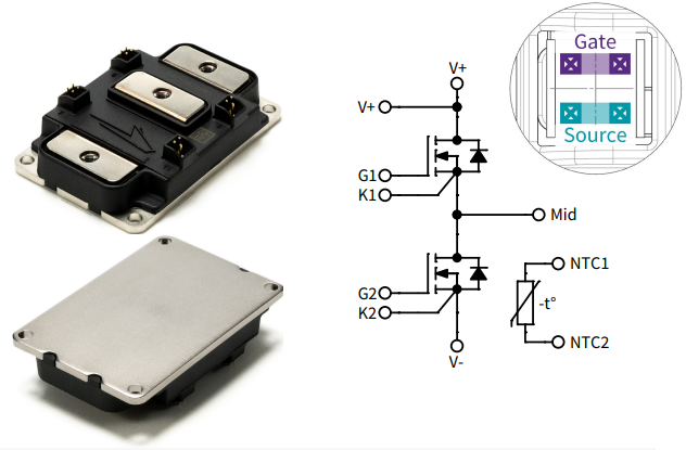
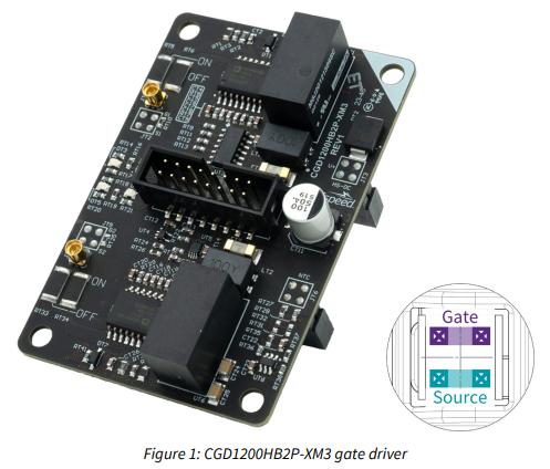
You are correct that the CAB450M12XM3 has an inline gate pin configuration, and the CGD1200HB2P-XM3 is the recommended gate driver for it. For future reference, an easy way to validate the gate pin configuration is to refer to the gate pin diagram on the first page of every XM module datasheet. For instance, the below picture is from the CAB450M12XM3 datasheet and shows the inline pin configuration in the top right. The user guide for the CGD1200HB2P-XM3 gate driver similarly shows the inline gate pin diagram as shown below.
CAB450M12XM3 Datasheet
CGD1200HB2P-XM3 User Guide
Thanks,
Chris N.
0 -
Thanks, Chris. I appreciate your help.
I am currently finalizing my PCB design, and if I need any further details regarding Wolfspeed modules, I will reach out to you.
Thanks again.
Best regards,
Sachith0