
SpeedFit™ Design Simulator
Simulate and evaluate the performance of SiC-based power circuits and determine the right SiC device in seconds.
Start a SimulationCRD25DA12N-FMC

Bought a new CRD25DA12N-FMC and trying to get it to run. Connect the USB to CAN port through a NI USB adapter. When sending package on the user GUI, there is no response. I also found an unexpected open circuit on the +5VISO signal between the CAN port J4 (pin 9) and CAN connector J5 (pin 1). Is this normal?
I also tried jumping them with a jumper wire, then I got the 5V between J5.1 and 4. Still no response. Pleease advise what could be the issue? Thanks.
Comments
-
Thank you for your post, it has been approved and we will respond as soon as possible.
0 -
Hello shengj2002,
I'm sorry to hear about your issues. I addressed your topics individually below.
- All CRD25DA12N-FMC reference designs go through a burn-in process before shipping out. This burn-in involves operating the system at full power and communicating with it through the CAN interface. Considering the CAN port is validated on all the units before shipment, I'm surprised by your issue, but I have more suggestions to try to get this working for you.
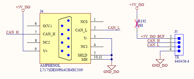
- J5 is intended for daisy-chaining additional CAN hardware such as having an input active front end (AFE) and inverter on the same CAN bus so that they can both be operated from the same host computer. In the daisy-chained configuration, each board would have its own dedicated isolated +5V rail. For this reason, a 0ohm resistor is unpopulated by default (R192) which means the +5V_ISO rail is not connected to J5 by default. This is the expected behavior, and the relevant schematic is shown below. It's recommended to use J4 for the CAN communication, as this is what is used for internal testing and most CAN-to-USB adapters have a DP9 output.
- Some DB9 cables will flip TX/RX connections, so it's important to make sure the cable is correct for interfacing with the board.
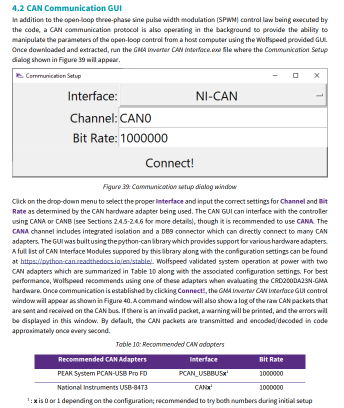
- Which NI-CAN adapter are you using? This reference design interfaces with the National Instruments USB-8473, but not all NI adapters have been tested. There is some additional information about the connections in the Section 4.2 of the PRD-09623 (snipped below).
- The CRD25DA12N-FMC needs to be powered on with +12V through the input barrel jack when communicating with it. Similarly, the correct interface and channel must be selected in the CAN communication setup window.
I hope these suggestions help you to identify the issue!
Thanks,
Chris N.
0 -
Hello shengj2002,
I hope that this answered your question. I will close this discussion for now but if you have a follow up question, please "Start a New Discussion" and we would be glad to support you further.
Thanks,
Chris N.
0