
SpeedFit™ Design Simulator
Simulate and evaluate the performance of SiC-based power circuits and determine the right SiC device in seconds.
Start a SimulationThermal Resistance of CAB7R5A23GM4T

My question is referring to your CAB7R5A23GM4T. It lists a Rth(j-hs) = 0.145C/W. I assume this also includes the thermal resistance of the TIM? What percentage of this 0.145C/W comprises the TIM. Your application note PRD-0933 stated that the TIM can be up to 60% of the total. Can I ask what is the TIM thermal resistance of this module?
Thank you!
Comments
-
Thank you for your post, it has been approved and we will respond as soon as possible.
0 -
Hello,
You are correct that assuming the Rth JH value listed on the datasheet includes the TIM layer, and it also includes 2 mm of aluminum heatsink. Our measurements point to the methodology described in AQG324, and that is where the diagram below is found.
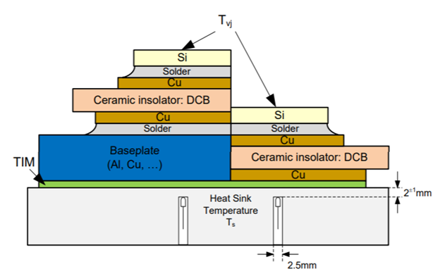
The TIM layer can make a substantial contribution to the thermal stack’s overall thermal resistance, as called out in our application note. The exact percentage is dependent on a variety of factors, which mainly have to do with the module’s material properties and construction. It is also dependent somewhat on the cooling solution used, since even though Rth JH is not a system level measurement, the measurement does not occur in a vacuum.
It is difficult to derive the exact contribution of the TIM layer to the thermal stack, but it can be estimated analytically using structure functions, which are a graphical representations of the thermal stack’s Cauer network. Based on the structure functions for this measurement, the TIM layer comprises approximately 54% of the thermal stack, with the module and heatsink making up the remaining percentage of the thermal resistance. It's worth noting that there is also thermal contact resistance between material layers, which a good TIM helps reduce, but cannot fully elimate it. This thermal contact resistance is included in the measurements, and its contribution is generally seen in the TIM's thermal resistance.
Best Regards,
Dustin
0 -
Thank you Dustin!
I assume the left half of the diagram depicts your modules with the baseplate and the right hand side is your
baseplate-less modules? Is this correct?
0