
SpeedFit™ Design Simulator
Simulate and evaluate the performance of SiC-based power circuits and determine the right SiC device in seconds.
Start a SimulationCAS530M12BM3 devices based inductive load simulation

Hi Wolfspeed team,
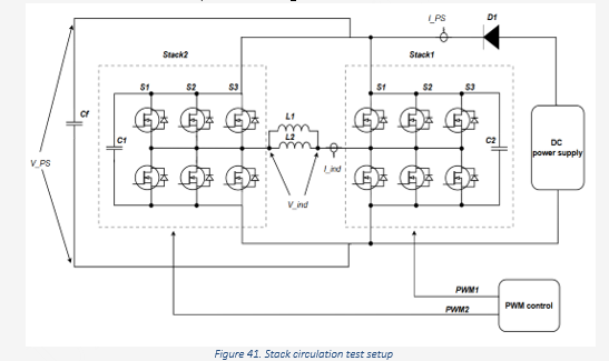
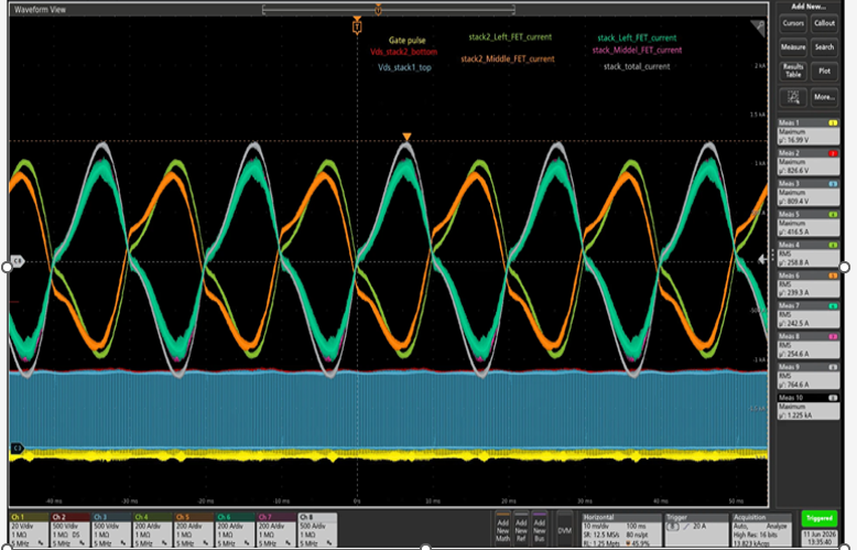
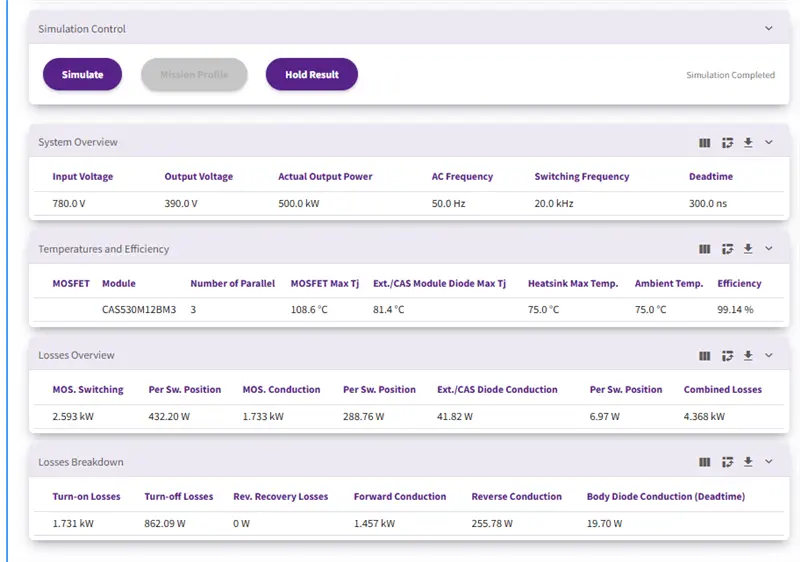
We did simulation and actual test with CAS530M12BM3 device three parallel per stack, H-bridge configuration with inductive load. Based on simulation results we get 1.45 KW loss where actual loss is 1.7KW. I have observe that there are very low power loss of diode which is 14W per stack. It this simulation tools consider inductive load or not?
Furthermore, during simulation many times observe the simulation give us an error after some trials with same parameter. Is this simulation tools works on limited attempt or some specific time limit or not?
The simulation parameter are given below
Rg ON - 2.2ohm
Rg OFF - 1.1ohm
DC 780V
Output current - 740A
Heatsink temp - 75 degree fixed
Comments
-
Thank you for your post, it has been approved and we will respond as soon as possible.
0 -
Hi Ashraf,
Typically, there are two major sources of variation between a PLECS simulation and reality. First is that the PLECS model represents a typical part, and there will always be device to device variance. The delta between your measured and simulated results, however, is quite large, and I wouldn't want to simply ignore it in this case.
The second possibility is a difference in system model. Because the SpeedFit simulations are designed to be quite generic, there is a strong possibility is a poor representation of you actual system. There is likely a big difference in the simulated control scheme, system parameters, and device currents. Additionally, if your cooling system is not well represented in the model, there could be a major difference in predicted and actual junction temperature (and conduction losses are especially dependent on TJ).
In this case, I'm seeing from your measurement that using an ideal sinusoid (which is the approach used in SpeedFit) is probably a poor approximation of your actual system dynamics, and that could be playing a major role in your total losses. I'd probably recommend moving away from SpeedFit and creating a new model in PLECS offline (Plexim is quite generous with trial licenses if you'd like to give it a try). I'd be happy to assist you in building a system simulation which better represents your converter if you'd like to do so.
Thanks,
Blake0