
SpeedFit™ Design Simulator
Simulate and evaluate the performance of SiC-based power circuits and determine the right SiC device in seconds.
Start a SimulationIBB020A33GM4的电气间隙及爬电距离

Comments
-
Thank you for your post, it has been approved and we will respond as soon as possible.
0 -
Hello, muyi
The clearance value limit is set by the peak voltage, and creepage value limit is set by the intended working voltage. They are all taken at Pollution Level 2 and Material Group 1 referring to UL 61800-5-1, UL 840, and IPC-2221A.
0 -
IBB020A33GM4属于SST应用,参照什么标准?为什么Terminal to Terminal的电气间隙会大于Terminal to Heatsink?
0 -
参考UL61800-5-1,如下表,3.3kV clearance要求2.3mm,考虑5km海拔修正系数1.5倍,需要最小电气间隙为3.45mm。
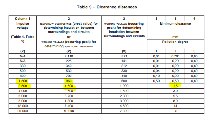
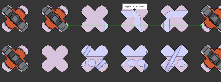
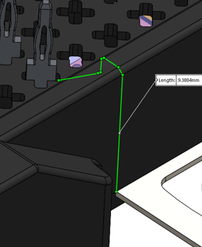
模块Terminal to terminal和Terminal to heatsink最小电气间隙分别约为10.63mm和9.38mm,均满足标准要求。
 0
-
1、SST应用中Impulse voltage的电压如何考虑?2.3mm是根据column1还是column2计算的?
2、根据IBB020A33GM4的datasheet标明:模块的电气间隙Terminal to terminal为12.5mm和Terminal to heatsink为10mm,但是根据提供的【IBB020A33GM4-All-CAD-Models】文件测量,模块的电气间隙Terminal to terminal约为11mm和Terminal to heatsink约为13.6mm,与您计算的差异原因?
0 -
1/ 在SST的应用中的输入impulse voltage,通常是额定输入电压的近10倍,不会直接作为模块的绝缘选型参考。系统输入端需要增加防雷/过压钳位等保护,其传导到变换器上的残压会低很多。
上面提到的2.3mm是根据表中column 1中3.3kV,PD2列查的表。
2/ 可能测试位置点不一样,以datasheet为准。这里Terminal to heatsink是指到模块侧面的安装固定片(安装后与散热器电气连接),而不是到模块底面。
0 -
1、如果没有冲击电压,为什么不按照column 2来计算?
2、由于系统原因无法上传照片,【模块的电气间隙Terminal to terminal约为11mm和Terminal to heatsink约为13.6mm】尺寸是按照您展示的照片计算的,但您的照片【10.63mm】尺寸只是pin针到另一个pin针附近的壳体,实际距离偏小;【9.38mm】尺寸应该只是壳体侧壁的距离,实际距离偏小
0 -
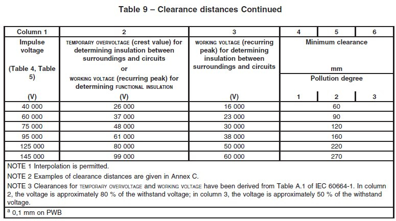
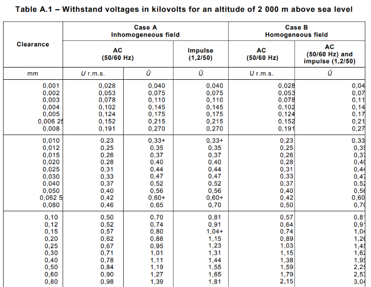
这里column2是根据IEC 60664-1 table A.1的withstand voltage(工频电压峰值)计算来的。而我们设计参考的impulse的值就可以了,实际通常有充分的裕量。
 0
-
好的,谢谢。
0