
SpeedFit™ Design Simulator
Simulate and evaluate the performance of SiC-based power circuits and determine the right SiC device in seconds.
Start a SimulationDesign Considerations for Designing with Cree SiC Modules

Hi Wolfspeed team,
These pictures are from the Design Considerations for Designing with Cree SiC Modules Part 2. Our customer wants to know how to measure the parasitic inductance of this Capacitor board. Whether it is necessary to short-circuit the module connection point holes at the right side?
Thanks,
Jeremy Zhang
Comments
-
Hi Jeremy,
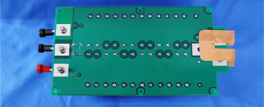
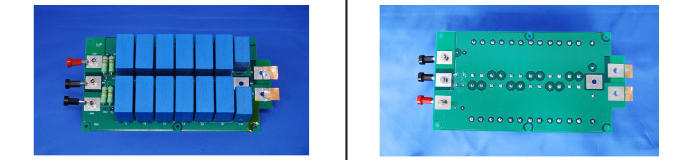
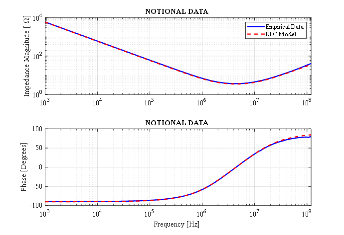
To measure the partial commutation inductance of this capacitor board, it is recommended to measure from the D1 terminal to the S2 terminal (see Fig 1 and Fig 2 below) with an impedance analyzer across frequency. This measurement will yield the total impedance from the module to the bulk capacitors. The impedance profile will be a series RLC response, and the effective inductance can be determined by calculating the inductance (Z = jwL) above the resonance or by fitting an RLC impedance model to the impedance data (see an example of this in Fig 3).
During the measurement, the terminals should not be shorted. I understand this confusion likely comes from Figure 22 in the referenced application note. This configuration with the shorted terminals was used to remove the contributions of the attached copper and the D1 and S2 terminal pads. In actual operation, the D1 and S2 terminals will interface directly with the module (Fig 1) and that contribution is included in the commutation inductance of the module. Because the inductance of the bus structure is so low, the contribution of the D1/S2 terminals can be significant. Thus, when performing this measurement, it's important to consider how the fixture attaches to the D1/S2 terminals and how the short compensation is performed.
Please let me know if you need further explanation or have any additional questions.
Thanks,
Brian D.
Fig 1

Fig 2
Fig 3
 0
0 -
Hi Brain,
Thanks for your help! If we just want to measurement bare capacitor only, measure from D1 terminal to S2 terminal is still or not?
Best Regards,
Jeremy Zhang
0 -
Hi Jeremy,
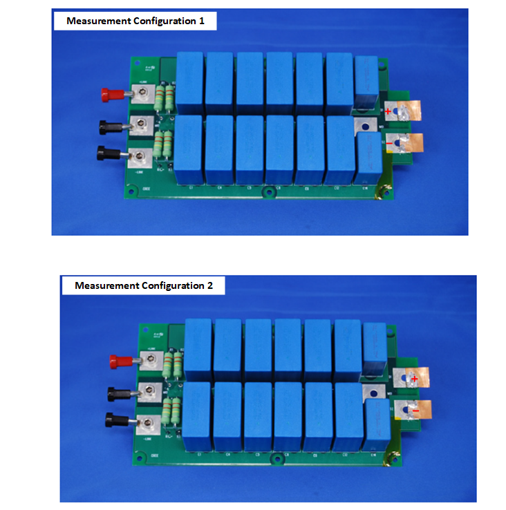
Yes -- measure from D1 to S2. However, the ESL will depend on where you attach your impedance measurement. For example, see measurement configurations 1 and 2 below. The red '+' and '-' indicates where you apply your impedance measurement. In 'configuration 1', the +/- are close to the capacitors. In 'configuration 2', the +/- are far from the capacitors, and the ESL will be higher. So, you need to be strategic when you apply your impedance analyzer stimulus to get the measurement you want.
Thanks,
Brian D.
 0
0 -
Hi Brain,
Thank you for the hard work! All questions have been answered!
Happy Halloween!
Jeremy Zhang
0