
SpeedFit™ Design Simulator
Simulate and evaluate the performance of SiC-based power circuits and determine the right SiC device in seconds.
Start a SimulationInquiry About CRD25DA12N-FMC Resolver Compatibility and Protections
Dear Wolfspeed Support Team,
I recently purchased and have been working with the CRD25DA12N-FMC 25 kW Three-Phase Inverter. I have a few questions regarding resolver compatibility and system protections, and I’d appreciate your guidance:
- Excitation Signal Voltage:
I measured the voltage magnitude at the EXC P and EXC N terminals as 15V. Can you confirm if this is the expected excitation signal level? - Resolver Compatibility:
I plan to use the TE 2367237-1 resolver (Size 21, 3 pole-pair, hollow-shaft) with the following specs:- Excitation (input) voltage: 3 V (rms)
- Typical frequency: 8 kHz
- Max input current: 40 mA
The current excitation signal appears incompatible with this resolver. Could you advise on how to modify either the software programming or hardware configuration (e.g., voltage reduction) to make it work with the J16 Resolver Connector?
- Protections Implemented:
Could you provide details on the hardware and software protections (e.g., overcurrent, overvoltage, thermal) integrated into the inverter board?
I’d greatly appreciate your prompt response to ensure seamless integration. Thank you for your support!
Best regards,
MT Faiz
Comments
-
Thank you for your post, it has been approved and we will respond as soon as possible.
 0
0 -
Hello MT Faiz,
- The starting firmware does not include resolver functionality by default, so this code must be added by the end user. Because of this, the measurement you are observing is simply the voltage rail of the excitation signal which is +15V as expected.
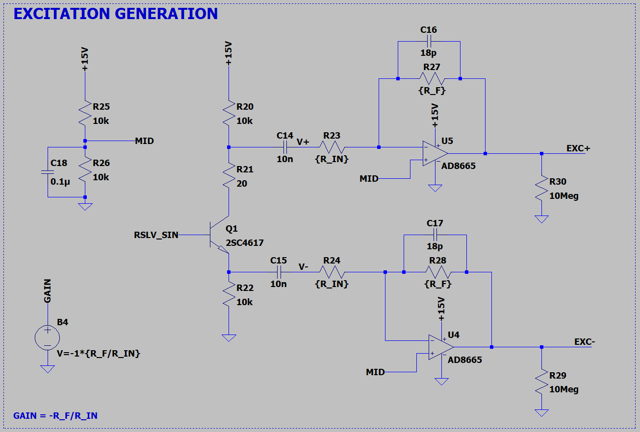
- I attached an LTspice simulation of the resolver excitation circuit. You can reduce the amplitude of the excitation signal by reducing the value of the feedback resistor "R_F" (R27 and R28 in the simulation schematic). The resolver circuit was originally optimized for 7 Vrms @ 10 kHz resolver circuits such as the Tamagawa TS2640N321E64. Since your operating requirements are similar, your resolver should work fine once the feedback resistors are adjusted. There are a few versions of the PCB, so I also attached the schematics of the different versions for you to easily make the modifications on your hardware. We are working on updating the website to allow for the different versions to more easily be downloaded.
- The board includes current sensors which can be used to identify overcurrent load conditions, and it includes a thermistor integrated into the power module which can be used to monitor heat sink temperature during operation. The board does not include integrated overvoltage protection.
Thanks,
Chris N.
0 -
Thank you for the clarification and sharing the LTspice simulation, schematics, and guidance on resolver excitation adjustments. Your explanation about the firmware, resistor modifications, and available sensing features is helpful. I appreciate the thorough response and the resources provided.
0 -
Hello MTFaiz,
I'm glad the response was useful. I will close this discussion for now but if you have a follow up question, please "Start a New Discussion" and we would be glad to support you further.
Thanks,
Chris N.
0