
SpeedFit™ Design Simulator
Simulate and evaluate the performance of SiC-based power circuits and determine the right SiC device in seconds.
Start a SimulationQuesting about CRD300DA12E-XM3 with CGD1700HB2M-UNA gate driver power supply

Hello Experts,
We were looking at the CGD1700HB2M-UNA schematic and we had a few more question on the UCC21710 gate driver power supply design.
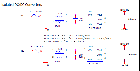
There is an isolated DC/DC converter (R12P21503D) which is +15v/-3v (93mA/185mA) which is used to generate the positive and negative voltage rails to turn On/Off the mosfet module.
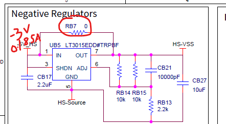
But we see that the output of this DC/DC converter are again given to voltage regulators, the LT3015EDD#TRPBF of the negative rail and the LT3082EDD#PBF for the positive rail, and then they go to the gate driver(UCC21710), Why is this done so? Using a higher current rated regulator(the LT3015 is rated for 1.5Amps) has no meaning if the input is current limited to a few mA? and, In case of the negative regulator , the input -3v (185mA), what is the purpose of RB7? As per the BOM RB7 is assembled and it would directly bypass the negative regulator?
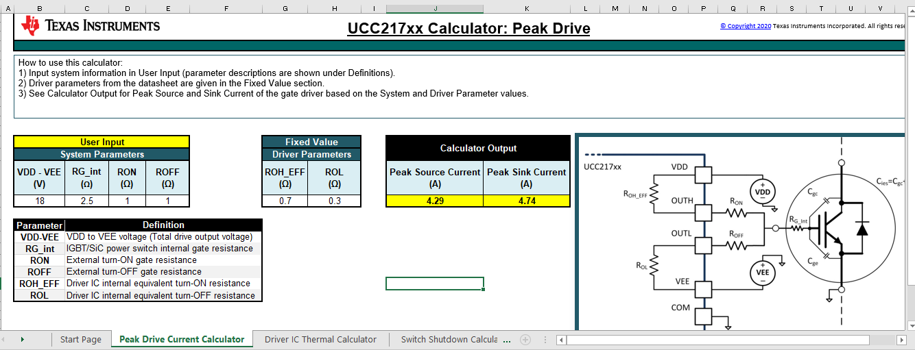
Texas instruments provides a tool to see what are the gate driver current requirements for UCC21710. Putting in the values that were in the CGD1700HB2M-UNA circuit we get a maximum source current of current of 4.29A and a maximum sink current of 4.7A. How are you achieving such high levels of current? I don't think the isolated DC/DC converter can achieve these currents even momentarily..
Could you kindly clarify on the above.
Thanks,
AK