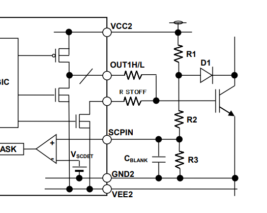
C3M0065090D のDESAT設定について
R_STOFFの定数設定はどのようにすればいいですか?
C3M0065090D の短絡保護にDESATを検討しています。
DESAT電圧はどのように設定すればいいですか?
VDS-ID特性より設定可能でしょうか?
また、DESAT検出時はソフトターンオフでゆっくり停止させようと考えています。図のOUT1H/OUT1Lをハイインピーダンスとし、
R_STOFFでゆっくりゲート電荷を引き抜く予定です。
R_STOFFの定数設定はどのようにすればいいですか?
ゲート電荷の放電時間、ゲート電圧のコントロールなど、具体的な計算式、参考になる特性データ等がありましたらご提供お願いいたします。
Comments
-
Thank you for your post, it has been approved and we will respond as soon as possible.
0 -
Is this the correct translation to your question :
"How should I set the R_STOFF constant?
We are considering DESAT for short circuit protection of C3M0065090D.
How should I set the DESAT voltage?
Is it possible to set it based on VDS-ID characteristics?
Also, I am thinking of using a soft turn-off to slowly stop the motor when DESAT is detected. Set OUT1H/OUT1L in the figure to high impedance,
We plan to slowly draw out the gate charge with R_STOFF.
How should I set the R_STOFF constant?
If you have any specific calculation formulas or reference characteristic data, such as gate charge discharge time or gate voltage control, please provide them."
0 -
返信ありがとうございます。
0 -
- The Rssd is used to adjust the soft-shutdown at the DESAT is triggered, lager resistance => slower shutdown => lower Vds overshoot and longer protection timing. it is a trade-off, selecting a proper Rssd based on the tests and validations on the actual hardware. The basic principle is to ensure that the Vds overshoot voltage at the DESAT is triggered less than the Vdsmax of the SiC MOSFET, and then select a Rssd as smaller as possible for faster protection.
- How to set the DESAT threshold?
- Threshold voltage – select a high enough voltage that it will never trip during non-short circuit operation. Take into account any expected overload conditions that the converter is expected to see, and consider the max RDSON at 175C. Although we don’t typically publish this number, you can scale from the 25C nominal and max values. Rds(on)nom175C * (Rds(on)max25c / Rds(on)nom25C). There is very little impact on the response time if you set the voltage at 10V vs. 15V for example because in a short circuit condition, the drain voltage exceeds both voltages within a few ns of each other.
- Select a DESAT capacitor that is at least 56-100pF to improve noise immunity and place it directly next to the DESAT pin of the gate driver chip. If the charging current from the driver is too small to provide the required timing with this size capacitor, add an external pull-up to the +15V rail to add additional charging current;
- Layout – in addition to placing the DESAT capacitor directly next to the IC, you need to be mindful of the routing. It is a sensitive signal that can get disturbed by gate pulses or parasitic coupling. Place the blocking diodes as close to the MOSFET drain as possible, and the remaining components as close to the driver IC as possible. The kelvin source pour should cover the trace starting at the anode end of the diode closest to the IC – do not place the source pour over the junction between the blocking diodes or near the drain as we never would.
- The protection timing is the most important factor. The blanking and detection time should be set to 300-500ns combined to allow ~500ns to turn off the current. Exact timing requirements should be based on the short-circuit curves at the maximum bus voltage you will operate at, for example, if you use a 1200V SiC MOSFET with the maximum DC bus voltage less than 800V, you should ensure that the total overcurrent duration timing to be less than 1~1.5uS.
0 -
なるほど
ありがとうございます
0 -
Hi, I hope that this answered your question. I will close this discussion for now but if you have a follow up question, please "Start a New Discussion" and we would be glad to support you further.
0


